


Other Parts Discussed in Thread: UCC256403
Hi team,
We’ve got questions on UCC256402’s external shutdown feature. Would you please take a look below, and provide answers?
[Q1] To enable external shutdown, I believe FBreplica should be less than BMT (FBLessThanBMT). How can we determine this BMT value? Is there a way to measure this value, or can we calculate it numerically?
[Q2] To enable external shutdown, FBreplica should be lower than SSreplica as well. How this SSreplica determined? Is it 3.5V fixed continuously, or the min is fix to be 3.5V?
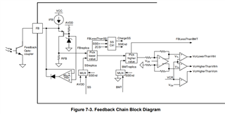
[Q3] Related to Q2, does BLK-voltage affect SS-voltage? From functional block diagram, it looks independent.
Best regards,
Kurumi
