Because of the holidays, TI E2E™ design support forum responses will be delayed from Dec. 25 through Jan. 2. Thank you for your patience.

This thread has been locked.

If you have a related question, please click the "Ask a related question" button in the top right corner. The newly created question will be automatically linked to this question.

TPS543B20: Ripple Noise Reduction using snubber circuit

Part Number: TPS543B20

Hi team,

I am using TPS543B20RVFT in my design with the below configuration.

Vin=5V

Vout=0.84V

Iout=25A

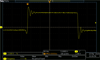
I observe voltage overshoot and undershoot at the switching output pin of the regulator. 

I have attached a snapshot of the circuit design and probed waveforms. The waveforms are measured when no Snubber circuit is mounted. C433 and R377.

Please provide your suggestions on the same.
  • Hello Shifali, 

    The SW node ringing appears to be a result of high loop inductance. This could be caused by a few things, one of which being the measurement method. A passive probe with a long loop between SW & GND can cause this issue to appear larger on the scope than it may really be.

    A few things to note: It is required to include a high frequency by-pass capacitor (10nF-100nF) between VIN and GND as close to the pin as possible.

    Furthermore, SW node ringing will be reduced by populating the snubber circuit.

    Best regards,

    Britton

  • Hi Britton,

    The commonly used snubber circuit has resistor connected to switching point and capacitor connected between resistor and ground. But the TI webench shows different snubber circuit which has capacitor connected to switching point. Which is the correct approach.

    Can we use the regular snubber circuit or consider the TI webench circuit. 

  • Hi Britton,

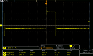
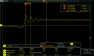
    I also mounted the snubber circuit and checked for the ripples.

    I mounted R377 with 1nF capacitor and mounted 0E in place of C433.Attached the waveform snapshot . Please suggest some snubber values.

  • Hi Shifali, 

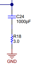
    The snubber can be connected from SW, to Capacitor, to Resistor, to GND (pictured below). Typically, we implement a 1nF capacitor along with a small resistance (1-3 Ohms).

    In order to optimize the snubber for your application, you can refer to the following post which outlines methodology for calculating an RC snubber. 

    Power Tips: Calculate an R-C snubber in seven steps - Power management - Technical articles - TI E2E support forums

    Best regards,

    Britton