HI all,
The version R0B of PCB has come back, Because of some reasons, we can’t have the sifos BT test now. We use the BT loader to test the eight BT ports. They all can work normally.
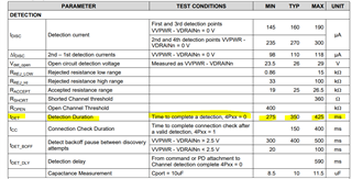
When we have the sifos AF/AT test for the eight BT ports, the parameter of Detection_Time_Tdet for 42 and 43 port is fail ,the value is 750 which you can see the report. Also We use the AT loader to test the eight BT ports. They all can work normally.
Now, I have some questions as follow,
- The attachment is the design of PSE card, we have move the sensor resistors and MOSFETs near the TPS23881 chip,can you help me to find some other resons?
- If the parameter of Detection_Time_Tdet is fail, is there any question for customer use ?
Thanks.