


Hi,
The diagram below is from the document SLUA903 - Data Flash Configuration Settings Pertinent to Learning Cycle Completion
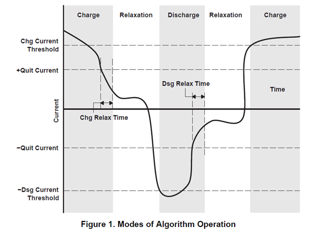
Can someone explain where on the diagram the Charge Term Taper Current would be?
Paragraph 2.4 of the document states that the Chg Current Threshold should be set lower than the Charge Term Taper Current, but I can't make sense of this.
Many thanks,
Adrian
