I am developing a DC-DC buck converter using a transformer to separate the primary and secondary GNDs
I know the approximate circuit configuration, but I'm not sure how to set up pins 1 and 2 / 15 and 16 of TL494 for constant voltage and constant current output
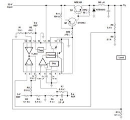
If the DC-DC converter is configured regardless of insulation, it can be configured like a Typical Application using short characteristics at both ends of OP-AMP as described in the datasheet, but I wonder if the MOSFET should change the switching level to make the secondary voltage constant.
And I want to know how to connect both ends of the OP-AMP for constant voltage and constant current output, and how the duty ratio changes when the switch is turned on/off.
The output we want is 12V 30A 360W output (24V input)

-
Ask a related question
What is a related question?A related question is a question created from another question. When the related question is created, it will be automatically linked to the original question.