This thread has been locked.

If you have a related question, please click the "Ask a related question" button in the top right corner. The newly created question will be automatically linked to this question.

BQ27426: SOC jumps issue at 0℃

Part Number: BQ27426
Other Parts Discussed in Thread: GPCRB

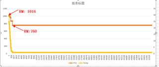
我们在0℃的环境下,做了1A电流的持续放电测试,确认RM和SOC的变化值,发现了异常的变化。

We did a continuous discharge test with 1A current at 0°C to confirm the change in RM and SOC values and found an abnormal change.

请协助确认下出现如下两种错误情况的原因:

Please assist in confirming the cause of the two error conditions as follows:

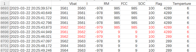
1. 日志1中,1A放电开始后,从0℃上升到6℃时,FCC和RM突然变成了一个异常值,并且持续到了测试结束。

1. In log1, after the 1A discharge started, the FCC and RM suddenly became an abnormal value when it rose from 0°C to 6°C and continued until the end of the test.

4532.log1.csv

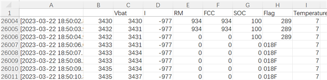
2. 日志2中,1A放电开始后,在温度是7℃时,FCC,RM,SOC突变为0。

2. In log 2, the FCC, RM, and SOC suddenly change to 0 when the temperature is 7°C after the start of 1A discharge.

7103.log2.csv

Thanks

  • Hello TI engineers, is there any update?

  • This looks like the gauge calculated cell resistance at low temperature high enough to cause a voltage drop close to or below Terminate Voltage even for a cell state equaling a full charge, hence FCC and RM are extremely small.

    What's the exact configuration?

  • 我们使用的是新的电池,内阻很小。

    配置方面,温度设定为外部输入的方式,其余的配置参考附件的FS文件。请帮忙确认。

    We use a new battery with very little internal resistance.

    For the configuration, the temperature is set as an external input and the rest of the configuration refers to the attached file. Please help to confirm.0426_2_02-bq27426G1_CXB_OBD_ECMM_CC1200_R1_0320_130mAh_2s_NoUpdate.gm.zip

  • The initial load is very high (977mA). You can see that the cell voltage drops significantly and then starts to rise, even though the load doesn't change. This is due to heat generated inside the cell. The gauge needs to model this. However, the configuration that you attached uses default values for this temperature model, which are not appropriate. I changed this so that the gauge's simulation matches the observed rise in temperature, which fixes the SOC jump to 0 in my simulations.

    Please set the following parameters:

    "Gas Gauging","State","T Rise","94","Num"
    "Gas Gauging","State","T Time Constant","801","s"

  • 感谢回复,我们正在尝试导入这两个修改进行测试。但我们在未导入这个参数的设定前,尝试使用老化后的电池在0℃下静置设备时,发现FCC产生了较大的变化(大幅变小),这个是合理的吗?是什么造成了这个变化?我们测试的新电池未出现大幅变化的情况。

    Thanks for the reply, we are trying to import these two modifications for testing. However, when we try to use an aged battery to rest the device at 0°C before importing the settings for this parameter, we find that the FCC produces a large change (drastically smaller), is this reasonable? What caused this change? The new batteries we tested did not show a significant change.New battery.xlsx

     Old Battery.xlsx

  • If you use an aged cell, you will have to perform a learning cycle (with Update Status set to 0x03) before running any tests. FCC can change significantly at different temperatures. If the gauge learned the characteristics of an aged cell, it can have a big impact as in your example because cell voltage will drop below Terminate Voltage after significantly less passed charge if cell resistance is higher than for a new cell. 

  • Thanks for your reply.

    but there still some questions for this issue.

    1. The T rise change is from the default value of 20 to 94, what is the meaning of this change? What will be the change in the gauge?

    2. T Time Constant has been changed from 1000 to 801, what is the meaning of this change? What will happen to the gauge?

    3. Are there any other influences on the adjustment of these two parameters and parameters that need to be adjusted in co-operation?

  • #1: This value controls how much of the heat from the energy that is converted due to current through the cell resistance stays in the cell and causes the cell to heat up. Some of the heat will dissipate into the environment. The gauge estimates ambient temperature (it will use the last measurement from relax as a starting point) and then calculates how temperature rises due to the heat generated by the discharge current and cell resistance.

    #2: The T Time Constant controls how fast the heat dissipates.

    GPC calculates these values based on the current information, the calculated cell resistance, the ambient temperature (=start temperature) and the measured temperature rise. These values will only be correct, if the cell is in the final enclosure and the enclosure and cell aren't forced to a specific temperature, e.g. by forced air hitting the enclosure (because then the heat transfer is accelerated and the thermal model values will reflect this particular setup).

  • What is the basis for these two settings?
    Can we adjust them ourselves if they are adjusted again based on the actual test? If so, what should be the corresponding process?

  • The basis for these two settings are the log files submitted to GPCRb. GPCRb then calculates these settings.

    The bq27462 won't change these settings automatically. There is no process changing these with actual tests by the customer other than GPCRb. TI has internal tools that can be used but this requires that you submit the log files like in this thread. 

  • Hello Dominik,thanks for your always help.

    关于修改的T rise和T Time Constant,我们还有几个问题,请帮忙答复下。

    1. T rise和T Time Constant使用默认参数,是否在0.2C电流下放电没有问题?

    2. 修改后的T rise和T Time Constant,是按照我们提供的测试场景(1A电流)日志进行的优化,那如果典型场景是0.2C的话,是否还需要修改这两个参数?

    3. 修改这两个参数后,常温和高温放环境下的0.2C和1A电流下的SOC精度是否会有不好的影响?

    We have a few more questions about the modified T rise and T Time Constant, please help us to confirm them.

    1. Is there no problem discharging at 0.2C current using the default parameters for T rise and T Time Constant?

    2. The modified T rise and T Time Constant are optimised according to the test scenario (1A current) logs we provided.

    3. After modifying these two parameters, will the SOC accuracy at 0.2C and 1A current under ambient and high temperature discharge environments be adversely affected?

  • The lower the current, the less the effect of temp a and k because the energy converted into heat over the internal cell resistance is smaller (by a power of 2 because E = (U*I^2)*time. A 1A discharge is around 1C so a 0.2C load will have 1/5th of the current and 1/25th of the energy converted into heat so it likely won't have a noticeable effect (that's also why temp a and k are usually not critical for low loads).