This thread has been locked.

If you have a related question, please click the "Ask a related question" button in the top right corner. The newly created question will be automatically linked to this question.

LM5113: Leakage current from HS pin when all half bridge FETs are OFF

Part Number: LM5113

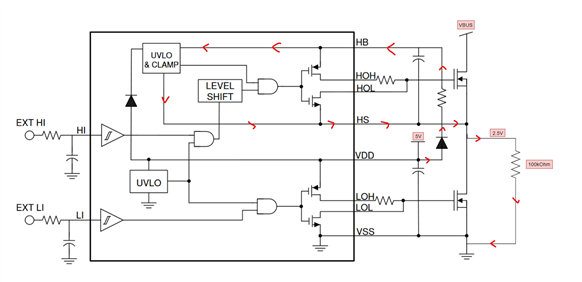
We have noticed that with VBUS at 0V or completely disconnected from a source, and with all FETs turned off, we see a sizeable 50uA coming from the HS pin, to the switch node, and then to ground, through any circuit elements living on the switch node..  We know it's not leakage through the bootsrap capacitor because we can DNP it a still see the 50uA.  We know the 50uA persists because we can add a 100kOhm resistor from the switch node to ground and see 2.5V develop and hold across it.  We know that the FETs are not the leakage path because the gate signals are low and VBUS is low or not connected to a power supply.

This 50uA is enough to charge our output capacitor bank in a few minutes and seems high.

Is this normal operation for the gate driver?

  • Hi Aidan,

    The LM5113-Q1 datasheet lists the max high-level output leakage current and max low-level leakage current as 1.5uA, so it looks like the leakage current you are observing is well above this threshold. 

    It looks like the diode connected between VDD and HB could be the cause of the leakage current. Could you share the part number for this diode?

    Best,

    Alex Weaver

  • The part number is the one recommended in the datasheet: BAT46WH,115

    We are considering removing the external diode completely because we have just seen from this forum post that the clamp circuit internal to the LM5113 does not work with an external bootstrap path.

    In multiple forum posts (here and here) it is stated that the external bootstrap cap is only used to improve startup speed.

    So I'm kind of adding an additional question here:

    1. It still seems that with the BAT46WH,115, this leakage path is high
    2. How exactly is the external bootstrap cap improving startup speed.
  • We have just removed the BAT46WH,115 completely from the circuit and are measuring about 22uA from the VSW through a 100kOhm resistor.

  • Hi Aidan,

    I believe the other engineer meant the external bootstrap diode helps with improving startup speed, not the external bootstrap cap. The purpose of adding an external diode is to allow charging of Cboot when forward biased, and prevent Cboot charges flowing back to VDD when reverse biased. 

    It seems as though removing the external diode helped reduce the leakage current, but it is still quite high. Is the image in the original post the same schematic as what is being used? If not, are you able to show the schematic? Please feel free to email it to if you do not want to post publicly.

    Best,

    Alex W