


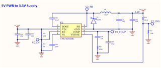

Using TPS54231 as a 5Vin to 3.3Vout supply. Device operates in low load mode for the majority of the time. What is interesting is that out of a sample of 27 PCBs only 3 exhibit the following behavior on startup. What I see is the 3.3V supply ramp up, stabilize, then enter a Sawtooth state. I don't see how this is even possible and curious to know what I might be seeing. The datasheet doesn't highlight such a behavior and this is not the ECO-mode either. On one of the PCBs, I can probe the COMP pin and cause the Sawtooth state to stop and enter a stable output. I can also change the value of the SS capacitor to a higher value and eliminate the Sawtooth state completely. On the other 2 PCBs the Sawtooth duration is a) much longer 40ms v. 5ms b) component changes to SS or COMP network do not eliminate the Sawtooth state. For these 2 PCBs applying an 8-ohm load stabilizes the output as the only remedy. Why do I have 24 PCBs that have a stable output at low load? 1 PCB that can be made stable with component changes? 2 PCBs that cannot be made stable at low load but stable at higher load?
Component changes that offer improvements mentioned above are changing R20 to 24.3k and changing C38 to 22nF. The scope image shows 5Vin (green), 3.3Vout (purple), and U2_COMP (blue). The time is takes to enter Sawtooth state is shown in the image as 9.44ms but it can be as high as 93.4ms. At the time at which the 3.3Vout starts Sawtooth waveform is exactly when the Mosfet stops switching. The 2nd scope images shows the mosfet completely stop switching as the 3.3Vout begins this Sawtooth waveform.
