This thread has been locked.

If you have a related question, please click the "Ask a related question" button in the top right corner. The newly created question will be automatically linked to this question.

BQ24125: STAT1 turns on and off periodically

Part Number: BQ24125

Hello team,

I received a inquiry from the customer. I have linked threads that I think are relevant.

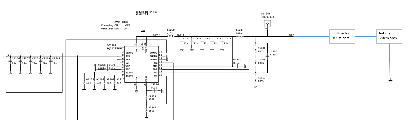
The customer states that STAT1 repeatedly turns on and off in approximately 1.2 second cycles while the battery is charging. The following information has been confirmed by the customer to date.

- The battery current changes similarly when it repeats ON/OFF.

- The internal resistance of the battery is less than 200 m ohm according to the data sheet

- A 100m ohm shunt resistor is inserted between RSNS and the battery pack for current measurement

Please let me know if there are any additional waveforms or schematics needed so that I can check with the customer.

Regards,

Masa

  • HI Masa,

    If this only occurs when the charger is close to termination, then the charger is most likely cycling between termination and recharge.  This can happen if the resistance between the BAT pin and battery pack or the pack itself is high resistance AND the ITERM is set too high.  That is because the ITERM*resistance > recharge threshold=50mV*(Rfbtop/Rfbbottom+1).  I recommend lowering ITERM if possible.  The cells will eventually charge.

    Regards,

    Jeff

  • Hello Jeff,

    Thanks for the support. The customer is asked to review this thread.

    Also, I received a question from the customer.

    As shown in the block diagram below, the customer thinks that the RSNS is controlling the charge by calculating the current from the difference in potential between the two ends (SNS BAT), but when the customer reads the related thread "BQ24125: STAT1 pin alternating between ON and OFF after first test", it can be read that it is controlling from the difference in potential between the two ends to the battery pack, which is correct?

    Regards,

    Masa

  • HI Masa,

    The constant current feedback loop uses the voltage across the SNS and BAT pins to regulate the charge current until the battery voltage rises close to regulation.  The constant voltage loop clamps the voltage at the top of the FB resistors (~PACK+) relative to charger GND (~PACK-) to the battery regulation voltage.

    Regards,

    Jeff

  • Hello Jeff,

    Thank you for your explanation. According to the customer's calculation, ITERM*resistance is less than the recharge threshold, could you please verify the calculation process?

    where,

    I CHARGE = 1.5 A, 

    I PRECHARGE = I TERM = 0.15A

    Rsns = 0.1 ohm

    I TERM*resistance = 0.015 V

    R fbtop = 300k ohm, Rfbbottom = 100k ohm

    recharge threshold = 50m V * (Rfbtop/Rfbbottom+1) = 50m V * ( 300k ohm /(100k ohm + 1)) = 0.15 V

    As a conclusion, I TERM*resistance < recharge threshold

    Also, when considering the resistance of the battery pack and multimeter

    I CHARGE = 1.5 A, 

    I PRECHARGE = I TERM = 0.15A

    Rsns = 0.4 ohm

    I TERM*resistance = 0.04 V

    R fbtop = 300k ohm, Rfbbottom = 100k ohm

    recharge threshold = 50m V * (Rfbtop/Rfbbottom+1) = 50m V * ( 300k ohm /(100k ohm + 1)) = 0.15 V

    As a conclusion, I TERM*resistance < recharge threshold

    As shown above, it seems that ITERM*resistance is less than the recharge threshold in both calculations. Is there any mistake in the calculation? Please let me know if you find anything.

    Regards,

    Masa

  • HI Masa,

    I am referring to undesired resistance of the board trace, connector, cables, pack protector FETs from the top of the FB resistor to the actual battery pack cells.  Rsns should be before the top of the FB resistor.

    Regards,

    Jeff

    • HI Jeff,

      Thanks for the support.

      This is just the simplified our circuit around BQ24125 . You can see that the Rsns is before the top of FB register. I’d appreciate it if you could check our circuit.
      If you need the waveform to check, please let me know which pins waveform are needed.


      Regards,

      Hiro
  • Hi Hiro,

    I see no issues with the schematic.  The charger regulates the battery voltage at top of FB resistors(Vfbtop) = Vcells +ICHG*(100mohm+200mohm).  If ITERM*(100mohm+200mohm)>VRCH, then when the charger terminates, the Vfbtop drops below BATREG and the charger restarts a new charge cycle until Vcells gets closer to VBATREG.

    Regards,

    Jeff