This thread has been locked.

If you have a related question, please click the "Ask a related question" button in the top right corner. The newly created question will be automatically linked to this question.

TPS631010: Maximum and minimum DutyCycle in FPWM Mode

Part Number: TPS631010
Other Parts Discussed in Thread: TPS61033

Hi,

Looking for the minimum and maximum DutyCycle of the TPS631010 in Forced PWM (FPWM) Mode. Or minimum On-Time of the switches.
Couldn't find it in the Datasheet December 2022, did i missed it?

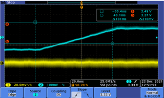
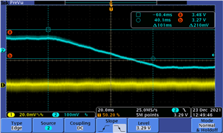
Would like to Boost from 3.2V to 3.6V and having the low noise behavior of the FPWM. Thats 11.1% DutyCycle or 55.5ns On-Time @2MHz for LowSide Switch.
Whats the limit of Forced PWM Mode and what is the behavior of the device when it reaches those. Does it switch to PFM even though pin MODE is set High?

Kind regards

  • Hi,

    The mode transition of TPS631010 has no matter with duty cycle.

    i think i know you concern that there will be larger noise in buck boost mode, right?  if so, that should be ok as the picture below. almost same output noise in boost and buck boost mode.

    it was a line sweep tests, the output voltage is 3.3V and device will go through buck, buck-boost and boost mode during this sweep.

    Regards

    Tao

  • Hi, there is a misunderstanding.
    My Voltages are:
    Input Voltage 3.2V
    Output Voltage 3.6V

    The Device is not only capable of transition between Boost and Buck-Boost.
    It can also transition between Power save Mode and forced PWM, selected by the Pin "MODE".
    This Pin selection between PFM and FPWM sugest, that it can run FPWM in all circumstances - but this is nearly impossible.
    Example: InputVoltage 3.55V, OutputVoltage 3.6V. The turn onTime of the Low Side Switch would need to be 7ns in order to sustain 2MHz PWM (That would be pretty impressiv).
    I imagine the device will change to PFM in such a circumstances.

    The Question is, does the device run in FPWM with 3.2Vinput and 3.6Voutput. But instead of Yes or No based on 1 measurement, the minimum OnTime would be of high value.
    Lets take the TPS61033 for example it has such a MODE pin aswell, page 6, chapter Power Switch. MAX value of Minimum on Time 65ns
    https://www.ti.com/lit/ds/symlink/tps61033.pdf?ts=1680091991689&ref_url=https%253A%252F%252Fwww.ti.com%252Fproduct%252FTPS61033

    The Problem we have, is that other devices on the marked start skipping edges or reducing frequency in order to maintain the minimum on time at this DutyCycle. This does change the EMC behavior of the circuit and used inductor (for our application it makes it worse). Voltageripple itself is not a problem.

  • Hi Christian,

    The control of BUBO is very different with boost converter. please do not take the TPS61033 as ref.

    For TPS631010, there is a mode seletion pin, when MODE pin is high level, the device will work in FPWM mode, which menas, no matter the conditons of Vout/Vin/Iout, TPS631010 always work with a fixed switching frequecy which is close to 2Mhz. If the mode PIN is low level, the device will work in PFM mode when load is light and the switching frequency will variant.

    TPS631010 has four power FET internal, when Vin is close to Vout, the switching period will be consisted by Boost energized phase, Boost de-energized phase and buck de-energized phase. the calculation of on time is much complicated.

    Regards

    Tao

  • Hi Tao,

    Thank you, i did not take in to account that the TPS631010 has four FET.

  • Hi  Christian,

    You are wlcome, thanks for considering TI's device..

    Regards

    Tao