This thread has been locked.

If you have a related question, please click the "Ask a related question" button in the top right corner. The newly created question will be automatically linked to this question.

UCD9090: In circuit programming tools requirements

Part Number: UCD9090
Other Parts Discussed in Thread: USB-TO-GPIO2,

Hi Experts,

Seeking your assistance on this query from Cx:

"We have to program UCD9090Q in circuit. We have testpoint on pins PMBUS_CLK ,PMBUS_DATA, PMBUS_ALERT , PMBUS_CNTRL.
Please define what programmer tool can we use as hardware and software too."

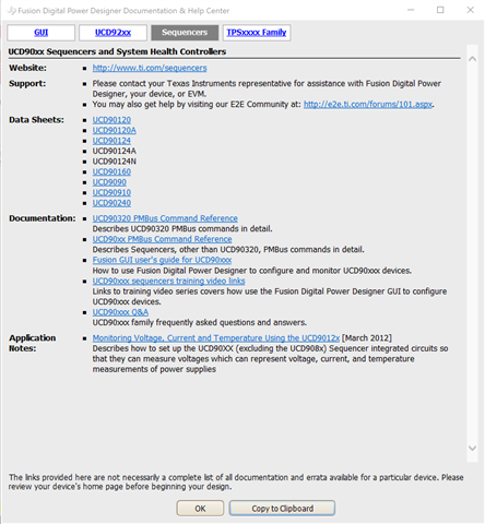
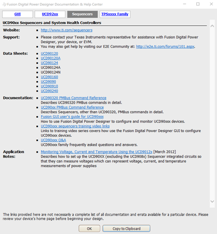
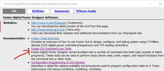
I am seeing THIS post. Do you think Fusion Digital Power Studio and USB-TO-GPIO2 are enough to the customer for their design?

Also, let me know what else we have to offer for the betterment of their design.

Thank you.

Regards,
Archie A.

  • Hi, Archie,

    FUSION_DIGITAL_POWER_DESIGNER (not Fusion Digital Power Studio), and USB-TO-GPIO2 tools used for UCD90xx devices.

    Regards

    Anne Ngo

    Texas Instruments

  • Thanks, Anne.

    Other than these tools, do you have any suggestions based on this request?

    We have to program UCD9090Q in circuit. We have testpoint on pins PMBUS_CLK ,PMBUS_DATA, PMBUS_ALERT , PMBUS_CNTRL.
    Please define what programmer tool can we use as hardware and software too.

    So, they can use those tools given the tests points they already designed, correct?

    Regards,
    Archie A.

  • Hi, Archie,

    If you use TI UCD9090 EVM board, when USB2GPIO2 adapter connects to device, the PMBUS_CLK, PMBUS_DATA, PMBUS_ALERT, and PMBUS_CTRL pins are connected to device's. If you don't use TI EVM board, then connect those pins to USB2GPIO2 adapter's pins according to USB-TO-GPIO2 user guide document. So yes, they can use those tools.

    Regards

    Anne Ngo.

    Texas Instruments

  • Hi Anne,

    Need your assistance again.

    We've read from several threads here that GUI's user's guide specific for UCD9090 is accessible within GUI itself. But couldn't find it in the app.  Is GUI user's guide downloadable separately now?

    We have attached the schematics part of the mentioned UCD9090, please check if this can work with the tools advised. Also, can you confirm if we can use UCD9XXX Device GUI / Flash / Firmware download to flash the sent content into our UCD9090?

    Without this information customer cannot decide what tool to order.

    Regards,
    Archie A.

    Attached.zip

  • Archie,

    UCD9XXX Device GUI/Flash/Firmware download, etc. are Fusion Digital Power Designer tools. In Fusion GUI window, click on Help menu, then you can Sequencer help files. 

    Regards

    Anne Ngo

    Texas Instruments

  • Hello Anne,

    Thank you. We still need your assistance please.

    The user just got the TI USB Interface adapter and tried to operate.

    I made a connection cable Likbelow :

                                                   adapter pin                        ucd9090 pin
    +3.3V                                                5                            V33A –V33D
    Ground                                             6                            GND
    PMBCTRL1/GPIO3                          7                            PMBUS_CNTRL
    PMBALERT/SMBALERT/GPIO2     8                            PMBUS_ALERT
    PMBC/SMBC/SCL/GPIO1               9                            PMBUS_CLK
    PMBD/SMBD/SDA/GPIO0             10                           PMBUS_DATA

    Tried to scan device in Rom Mode from UCD90xxx device GUI, but the result is

    see log

    Timestamp

    Message

    14:39:12.969

    Launching USB adapter (SAA) settings tool tool ...

    14:39:26.371

    Enabling PEC mode on USB adapter

    14:39:26.376

    SAA: SetPecMode (PEC): BAD DATA LENGTH

    14:39:26.388

    SAA: SetPecMode (PEC): BAD DATA LENGTH

    14:39:26.407

    SAA: SetPecMode (PEC): BAD DATA LENGTH

    14:39:26.413

    Looking for device in ROM mode at address 11d ...

    14:39:26.413

    Reading ROM version ...

    14:39:26.418

    SAA: BlockRead (Address 11d, Cmd 0xEC): BAD DATA LENGTH

    14:39:26.431

    SAA: SetPecMode (PEC): BAD DATA LENGTH

    14:39:26.447

    SAA: SetPecMode (PEC): BAD DATA LENGTH

    14:39:26.453

    Looking for device in ROM mode at address 66d ...

    14:39:26.453

    Reading ROM version ...

    14:39:26.458

    SAA: I2CWriteGeneric (0x84032020): BAD DATA LENGTH

    14:39:26.460

    No ROM detected

    14:41:07.573

    Launching dump flash file tool ...

    What else should we do to make it work? Thank you for your support.

    Regards,
    Archie A.

  • Hi, Archie,

    Do you any pullup resistors on DATA, CLK, and ALERT pins? If you don't have any pullup resistors on those pins, please change the adapter ALERT, CLOCK, and DATA pullup to 2.2 kΩ as shown in the below screenshot. UCD9090 might be in ROM mode, or Program mode => If device is not found in ROM mode scanning, then try to scan device in Program mode by click on "DEVICE_ID" link.

  • Hello Anne,

    I found a way how to program the UCD9090 with Fusion Design Online GUI. But it needs a lot of interactions. Is there any way to load a give .hex into the UCD9090 ? Can it be done from a win batch file ?  Is there  a command line interface?

    Thank you,

    Archie A.

  • Hi, Archie,

    Fusion GUI supports command line interface => it can be done from a win batch file. You can get the Command Line Tools document from Fusion GUI Help menu.

    Another tool to download the configuration is "Firmware & Configuration Download Tool". Deselect "Firmware Download" check box and select downloading Data Flash File.

    Regards

    Anne Ngo

    Texas Instruments