This thread has been locked.

If you have a related question, please click the "Ask a related question" button in the top right corner. The newly created question will be automatically linked to this question.

TPS629203: Power source impedance

Genius 15929 points
Part Number: TPS629203
Other Parts Discussed in Thread: , PSPICE-FOR-TI

Hi Experts,

Seeking your assistance about TPS629203DRLR. Customer is using this in a controller for LED lighting system. Below is the report:

The power source is 8.6V Max 1mA, which generated from the AC source through 470 Ohm resistance and diode.  So that this power source has 470 Ohm series resistance.  In fact I have to put 10 Ohm resistor between this power source and TPS629203 VIN terminal, otherwise this chip never started to work. I tried to make sure this with WEBENCH, however I could not set series resistance of Vsource more than 0.0011 Ohm.

Is there any way to modify this or insert external resistor between Vsource and Vin of TPS629203?

Thank you.

Regards,
Archie A.

  • Hi Archie A,

    Please order a TPS629203EVM and test it, or download PSpice for TI and run PSpice simulation. Or provide your schematic, I am not sure where are those 470ohm /10ohm?

    Thanks,

    Nancy

  • Hello Nancy,

    Thank you, customer Kaizuka, responded:

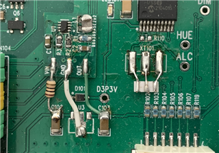
    I already have prototype as below photo. which has a patch board of TPS629203. So that I'll use PSpice-for-TI tool instead. You can see the 10 Ohm resistor, which is needed to start TPS629203 eventually.

    This controller went into production several years ago. The MCU uses a 2MHz CERALOCK, and the 3.3V power supply is about 0.9mA, so an LDO was enough.
    Last year, 2MHz CERALOCK was discontinued and only 4MHz CERALOCK was available, resulting in 3.3V current of 2mA.

    This controller utilizes existing indoor wiring to replace switches and lighting fixtures with brightness control types.
    Even when the lighting fixtures are turned on, the area near the zero cross point of the AC input is turned off to ensure power supply to the MCU.
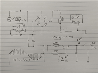
    The figure below shows the power supply circuit.


    Since the LED lighting goes down to a minimum of 4W, the power supply that can be taken is very weak, and the current limiting resistance of 470Ω is the minimum value for normal operation.

    The TPS629203 did not boot when I first connected VIN directly to the power source. I put in a 10 ohm resistor and it started.
    WEBENCH simulation confirmed that a considerable amount of current flows when it is turned on, so it is necessary to verify the safe operating range of 10Ω.

    ***

    For your assistance. Thank you.

    Regards,
    Archie A.

  • Hi Archie A,

    I still could not see the 10ohm location clearly. Schematic didn't show that 10ohm resistor location. Is C1 the input cap for TPS629203? Is 10ohm resistor series with positive side of C1? If yes, from the PCB file, the C1 should be placed as close as possible between pin6 and pin5. Current design C1 is far away from pin6 which will cause issue. TPS629203 didn't require 10ohm resistor on the input to start up. Please send me the schematic for TPS629203. From the PCB, the layout is very poor. The resistor R1 and C2 should swap the location. Move output cap as close as possible to pin 3 and inductor pad. Please refer to layout guide in the datasheet. You may order a TPS629203EVM to instead of your small TPS629203 board and connect to your input/output, then you will see if you need that 10ohm resistor.

    Hope this helps,

    Thanks,

    Nancy

  • Hello Nancy,

    Thank you. The customer just completed the circuit thru simulation:

    with the following reports:

    This circuit shows the 10 Ohm resistor as R6. The prototype circuit did not use EN function and without R6 it did not start correctly because of rush current.
    Since the power supply circuit of D8P6V is capable just feed around 0.6mA in average.
    So that if U1 start operation when the D8P6V is low voltage of UVLO(3V), U1 need around 1mA on VIN input and then D8P6V goes down.
    I could not explain why R6 works, but I change circuit to use EN function so as to start operation when the voltage of VIN goes around 6V.
    Eventually I found that R6 makes efficiency went down.  So I remove it.

    The user will re-spin the board with new parts placement according to data sheet suggestion.

    Regards,
    Archie A.

  • Hi Archie A,

    Thanks for letting us know. Using EN is a good way to turn on/off a buck converter. I will close this post.

    Thanks,

    Nancy