This thread has been locked.

If you have a related question, please click the "Ask a related question" button in the top right corner. The newly created question will be automatically linked to this question.

LM5158-Q1: Fast temperature rise

Part Number: LM5158-Q1
Other Parts Discussed in Thread: LM5157EVM-SEPIC, LM5158, LM5157

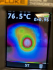
Hello, we are trying to use the LM5158-Q1 in the SEPIC topology to output 25V with a max of 1A. We built a prototype and tested with a half amp load and saw a very quick and large temperature rise. The chip heated up over 75°C in about 1 minute while dissipating this 12.5W.
 

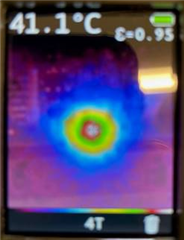
We compared this to the LM5157EVM-SEPIC eval board and saw that after about 15 minutes the temperature was still at only 41.1°C with a 12V, 1A load, so almost 12.5W dissipated.
I know that these aren't the exact same part, but they are similar and the user manual for the eval board says it can be used to evaluate the LM5158-Q1 so I figured it would be similar.

Do you have any suggestions as to why this may be happening?

Thanks

  • Hello Garrett,

    The driver of LM5158 is slower due to the higher voltage it can handle, so the power dissipation inside the IC is higher than in LM5157.

    Best regards,
    Brigitte

  • Hi Brigitte,

    Can the LM5158 be dropped into the eval board without any other modifications so that I can make a direct comparison? The difference between the eval board's temperature with the LM5157 and the temperature on my design is very large so I'm trying to figure if there are other improvements I could make.

    Thanks

    Garrett

  • Hello Garrett,

    Yes, you can drop in the LM5158 to the LM5157 EVM without any change.

    Best regards,
    Brigitte

  • While testing I tried replacing C8 on the eval board with the one I used in my design. It was a 0.1uF which is what the quick start sheet showed as the minimum value. This resulted in a 12 degree increase in temperature in half the time. Would it be better to have more capacitance here for heat or is it more likely an issue with the capacitor's Irms rating?

  • Hello Garrett,

    Please be aware that most ceramic capacitors loose capacitance if a DC voltage is present on them. You should therefore use a ceramic capacitor that is higher than the minimum recommended value as the calculation result is in this case ideal.

    In addition, the ripple current rating of the cap might influence this as well and if there is a lot ripple current on the cap which is the case if the value is low, there is more ripple current in the whole system, causing more losses.

    So yes, it is better to have a higher transfer capacitance.

    Best regards,
    Brigitte

  • I now have a lot of the same parts on my board and the eval board. It is a combination of what worked well on my board and what worked better with the eval board. I'm using the same chip (LM5158-Q1), same input capacitance, output capacitance, ac coupling capacitance, and diode. Same input and output voltage and the same load. I still see a 35°C difference in the temperature after about 20 minutes. This points to a layout problem, right? Just want to make sure y'all don't have any other suggestions for dissipating heat as far as part selection goes.

    Thanks

  • Hello Garrett,

    The temperature of your board is higher than the EVM temperature, right?

    This points to a layout difference. You might have a different copper thickness or less copper on top for example or less thermal vias on the thermal pad.

    Best regards,
    Brigitte

  • Alright thank you! That's what I thought it was but wanted to make sure.

    Thanks

    Garrett