This thread has been locked.

If you have a related question, please click the "Ask a related question" button in the top right corner. The newly created question will be automatically linked to this question.

LMG5200: Pulsed/CW mode

Part Number: LMG5200
Other Parts Discussed in Thread: SN6501,

Hi Team,

This inquiry of our customer is related to the other thread below.

e2e.ti.com/.../lmg5200-bootstrap-capacitor

According to our customer,

We are using the circuit in pulse mode to turn on/off the drain voltage of an GaN HPA. What alternative circuit option is available to a accomplish the pulsed/CW mode. Or how is the function accomplished using the charge pump to charge the bootstrap capacitor. Please send us a basic circuit schematic.

Regards,

Danilo

  • Hi Danilo,

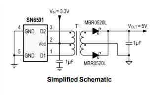
    Here is an isolated power supply option with SN6501:

    Vin would be the 5V bias rail, and Vout would connect to the bootstrap capacitor. Output ground would connect to SW node.

    It might also be worth adding a 5V Zener diode on the output to limit potential overshoots.


    Looking at the circuit diagram from your previous post, the output voltage of the LMG5200 appears to be 5V. Is that correct?

    Thanks,

    Travis

  • Hi Travis,

    Thank you for your suggestion. Please see the feedback of our customer below.

    This isn’t correct. 

    The output of the LMG5200 is 26V. 

    The duty cycle ranges from 1% to 100% (CW) with loads of 2.5 Amps  (for the GaN circuits). 

    How do we support CW operation AND current loads of lower current (like during gate bias discovery when we’re slowly increasing gate voltage while monitoring drain current)?

    Regards,

    Danilo

  • Hi Danilo,

    CW operation is going to add complexity. An isolated bias supply is likely the easiest option:

    https://www.ti.com/power-management/acdc-isolated-dcdc-switching-regulators/isolated-dcdc-converters-modules/overview.html

    It will provide voltage to the bootstrap capacitor regardless of duty cycle or output current.

    Thanks,

    Travis

  • Hi Travis,

    Our customer has a follow up inquiry below.

    Our Vout from this LMG5200 is a moderately heavy current 26VDC.

    We have numerous other regulators and supplies in the vicinity (+28, +26, +6, +5, +3.3, +1.2)…

    What value of V(bootstrap) must appear or be applied to (presumably) the HB(2) pin to maintain CW operation?

    Regards,

    Danilo

  • Hi Danilo,

    HB must be kept at +5V relative to HS. HS is internally connected to SW. The correct voltage on HB, for this application, would switch between +5V (relative to ground) and +31V (relative to ground) at the switching frequency of the PWM. That's why we recommend a floating supply.

    During CW operation, the HB pin would need to be kept at +31V (relative to ground). If you had a supply of greater than 31V, it may be possible to maintain the bootstrap voltage by connecting a resistor from the supply to HB, and placing a 5V Zener diode across HS & HB. However, this would be very inefficient during switching.

    Thanks,

    Travis