This thread has been locked.

If you have a related question, please click the "Ask a related question" button in the top right corner. The newly created question will be automatically linked to this question.

UCC38050: ZCD circuit question

Expert 1055 points
Part Number: UCC38050

Hi TI Experts,

I am recently designing a CRM boost converter. 

and I decide UCC38050 be the main solution.

and I have some questions about the ZCD circuit, could you please give me some suggestions?

1.

In figure 19, the primary and secondary winding has the same polarity.

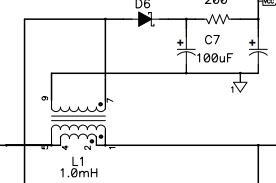
in figure 20, the primary and secondary winding hasn't the same polarity.

Which one is correct? 

2. In figure 19, how to decide the R14 and C12 values, the datasheet doesn't mention it, 


  • Hi Jack,

    Thank you for your interest in the UCC38050 PFC controller.

    1. The winding polarities are the same in both figures.

    2. Section 10.1.2 states that Rzc is chosen to limit maximum current into ZCD to 1mA. Since the clamp is 5V, choose Rzc > 5V/1mA, or 5kΩ. Since ZCD is sensitive to noise, Czc is added to filter out high frequency disturbances, yet not interfere with normal switching characteristics. The value of Czc is chosen so that the time constant of Rzc x Czc is in the range of 100's of nano-seconds (400ns in this case). 

    Best Regards,

    Ray

  • Hi  Ray,

    Thanks for your explanation.

    May I know how to decide the Czc?

    you said this capacitance will affect the time constant. 

    Do you have CrM SIMPLIS simulation could provide it to me?

    Jack

  • Hi Jack,

    The time constant I was referring to is Rzc x Czc. For instance, for the circuit in figure 19, tau = Rzc x Czc (R14 x C12) = 22e3 x 18e-12 = 396ns. Response time in this range won't interfere with normal operation. Additionally, this R x C combination provides a filter cutoff frequency at 1/(2 x pi x R x C) = 402kHz

    A simulation file does not exist for this product. However, a Mathcad tool is provided to assist with the primary calculations: https://www.ti.com/lit/zip/slvc018

    Regards,

    Ray 

  • Hi Ray,

    Thanks.

    I have two questions.

    1. how do you know the response time in this range won't interfere with the normal operation? can you explain in more detail?

    2. is it possible that I can know the peak value of the inductor's current? if I can, how to estimate the peak current?

    for example.

    the input voltage is sin(theta)

    when theta is 30 degrees, what's the inductor's peak current?

    when theta is 90 degrees, what's the inductor's peak current?

    Jack

  • Hi Jack,

    1. The controller operates in the 10's of kHz. For tau = 400nS, 3 x tau = 1.2us, which is well below the normal operating frequency.

    2.  The peak current formula is provided in equation (3) in the datasheet: [2 x sqrt (2) x Pin]/Vac(min). If you are trying to find the peak current relative to the non-rectified AC input waveform, you would take Ipk calculated above and multiply it by abs[sin(theta)]

    Regards,

    Ray

  • Hi Ray,

    About question 2, do you mean I can calculate by this method?

    2 x sqrt (2) x Pin]/(Vac*abs[sin(theta))

    Jack

  • Hi Jack,

    Yes, that appears correct.

    Ray

  • Hi Ray,

    Got it, thanks.

    Jack