This thread has been locked.

If you have a related question, please click the "Ask a related question" button in the top right corner. The newly created question will be automatically linked to this question.

LM5000: Power limitation in sinking current

Part Number: LM5000

Hello TI support

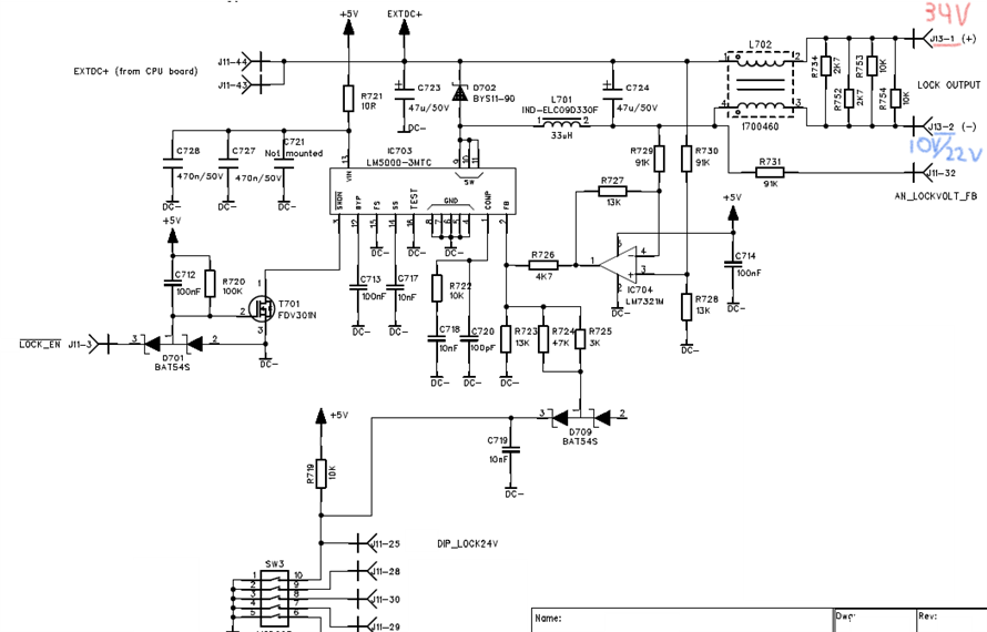
We have a board that uses LM5000-3MTC to regulate a voltage to either 10 V or 22 V depending on a setting of a DIP-switch that sets the reference to the feedback loop. The output from the LM5000 would be a fictive ground reference to a voltage source of 34 V (EXTDC+) resulting in 24 V or 12 V between the nodes.

Referring to the attached schema below, the power limitation on the +5V source is 2.5 W (5V@500mA) and on EXTDC+ it is 250 W.

In this setup the LM5000 would sink current, not source from SW pins on LM5000.

My question to you TI are:

  1. What is the power limiting in this setup?
  2. Is this design supported to be used with LM5000?

The schema:

Kind regards
Imre

  • Hello Imre,

    I doubt that there is a negative current limit available in LM5000. This means that the device can get damaged if the negative current gets too high, as I doubt that the temperature protection is fast enough to protect the switch.

    I will clarify if my assumption is correct, but expect some delay until I can verify or need to deny.

    But if there is something in the external system that limits the negative current to the same value as the positive is limited by the IC itself, I expect that the switch is ok with it.

    Best regards,
    Brigitte

  • Hello Brigitte

    Thank you, I will wait for your assumption clarification.

    So if LM5000 is sinking current, it it not limited by the available power on the VIN pin (#13) but limited by the "Switch Current Limit, ICL, {min, typ, max} = {1.35, 2.0, 2.7} A?

    Br
    Imre

  • Hello Imre,

    Possibly I misunderstood in which direction the current is going through the switch in your application. The device limits the current from SW to PGND as long as it is triangular (otherwise it might change too fast to be properly limited). If the current is flowing in this direction in your application, the current is limited by the ICL.

    Is this the current direction you spoke about?

    Best regards,
    Brigitte

  • Yes, it is this current direction I spoke about.

    In our application the current direction is negative, i.e., the current goes into SW and out on PGND.

  • Hi Imre,

    In typical use, current goes into SW and out on PGND, too.

    This circuit works.

    Best Regards,

    Feng Ji

  • Hi Feng Ji

    Please look at the schematics I attached on top of this ticket. The SW node in our application is used as a ground reference for an external voltage source. We use the LM5000 to change this ground reference to be able to have 12 V or 24 V between the external voltage source and this SW node. The current goes from the external voltage source and sinked via SW to PGND. Our external voltage source uses same ground as PGND.

    In typical use, Feng Ji, the current is sourced from SW, i.e., goes out and through the application load and back to PGND.

  • Hi Imre,

    This is indeed a buck converter with low side switch.

    https://shadyelectronics.com/low-side-buck-step-down-converter/

    LM5000 is a boost converter, and can also configured this way. Peak current limit is also valid for LM5000.

    Best Regards,

    Feng Ji

  • Ok Feng Ji. I think we drifted a little in the topic.

    Can I please ask you to read my origin first post where I have a schema attached? I had two questions, could you please try answer them if possible?

    Best regards
    Imre

  • Hello Imre,

    Let me try to answer your questions from the first post:

    1. The IC limits the current and therefore the power is limited by the current limit of the device. Dependent on the power dissipation inside the IC, thermal shutdown might kick in before the current limit is reached. So there is no simple answer to the power limit.

    2. Yes, the current flow is the same as in a boost converter and therefore you can use LM5000.

    Best regards,
    Brigitte

  • Thank you Brigitte for your answer.

    Sorry for not letting it go. Let me be clearer.

    Regarding "The IC limits the current and therefore the power is limited by the current limit of the device"
    I understand that but let me now go through it step by step. Please follow me in my statements below. Can you please confirm/deny each of them.

    1. The IC is power supplied via the VIN pin #13. In our application the feeding source to VIN is 5 V with maximum 500 mA as current limit. That gives us 2.5 W feeding power. Right?
    2. If we say the LM5000 is ideal with 100 % efficiency, the theoretical output power would be the same as the feeding power (if we are below Switch Current Limit, ICL). Right?
    3. The IC in our application is either set up to regulate 10 V or 22 V. In our application the output current would then be either 250 mA @ 10 V or 113.6 mA @ 22 V since these are all below the minimum value of Switch Current Limit, ICLRight?
    4. The current direction in the IC in our application is according to the red arrows in the picture below. I.e. it is sinking current. Right?

    You follow me still :)

    If we disregard the power dissipation and thermal shutdown (ideal conditions) in the IC, what would the power limiting be in this setup. Is it 250 mA @ 10 V / 113.6 mA @ 22 V or Switch Current Limit, ICL, {min, typ, max} = {1.35, 2.0, 2.7} A?

  • Hello Imre,

    1. The current consumption of the IC is not limited by your power supply, but by the current needed to supply the device, which is 2.5mA when not switching and then additionally the current needed to turn on the switch is added. For sure not 500mA.

    2. Yes in an ideal world.

    3. In an ideal world yes. In reality the output power is lower than the input power, so lower current in both cases.

    4. Yes, and this is exactly the same direction if used in the standard configuration as a boost converter.

    If your input supply is limited, this limits your output power and not the device.

    Best regards,
    Brigitte

  • Hello Brigitte

    Thank you for the exact answering. Then it is as I expected and got it verified with you.

    One last thing now. Then I can resolve my issue.

    Regarding the statement "If your input supply is limited, this limits your output power and not the device."

    Our input supply is limited to 5 V/500 mA using a LM2594M-5.0. In ideal world I am expecting maximum 250 mA @ 10 V or 113.6 mA @ 22 V from LM5000. In real world lesser. How come I am able to load 1150 mA @ 10 V and 1400 mA @ 22 V respectively before LM5000 can not be able to hold the reference level (10 V resp. 22 V)? It feels more like that it is the minimum value of the Switch Current Limit, ICL, {min, typ, max} = {1.35, 2.0, 2.7} A that sets the limit. It contradicts the statement I have quoted in italics. Can you please try to explain this?

    Keep in mind our current flowing direction. The power from our EXTDC+ (from CPU board) is for this application unlimited. In reality it is 34 V @ 9 A.

    Best regards
    Imre

  • Hello Imre,

    As the EXTDC+ is the supply for the power stage of the converter and it is not limited in power, the IC is limiting the power by its current limit.

    Best regards,
    Brigitte

  • Thank you for your patience holding out with me. Perfect, I now fully understand you answer.

    Best regards
    Imre