This thread has been locked.

If you have a related question, please click the "Ask a related question" button in the top right corner. The newly created question will be automatically linked to this question.

TPS62240 - measure output current

Other Parts Discussed in Thread: TPS62240

Hi,

I intend to use TPS62240 as a regulator for an MSP430 tool, which has to cover the supply range of all MSP430, so from 0,9V to 4V.

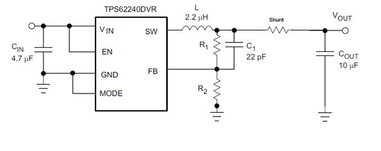
In the supply line of the prcessor, so between the TPS62240 and the MSP430 a series shunt resistor is going to be inserted to measure the current consumed by the MSP430 (high side current measurement).

Due to lack of experience with DC-DC switching regulators (till now I have been using TI LDOs for MSP430 power supply), I want to double check, if the DC-DC converter might have any negative influence on my current measurement later...

Thx

  • Hi,


    No, it should not be a problem. Let say if you put a small resistor in sereis at the output after the inductor to measure its voltage and use it for current measurements, it should be just fine.


    Thanks!

    Tahar

  • Hi,


    One more thing…to ovoid measuring inductor ripple current, place your resistor in series after the output cap to measure the DC load current to the MSP430.  Also I suggest using the INAxxx high side current measuring op-amps. See an example in this link:


    http://focus.ti.com/analog/docs/microsite.tsp?sectionId=560&tabId=2182&micrositeId=7


    Hope that helps and let me know if you have more questions


    Thanks!

    Tahar

  • One more recommendation: connect the output voltage sense point (input to the FB pin) after the output cap and inductor but before your current sense resistor.  This will guarantee stability of the device since the resistor won't be in series with the output caps.

    I recommend multiple sense resistors, each selectable with a jumper.  Say 1 Ohm, 10 Ohm, 1k, etc.  The MSP430 will draw very different levels of current and to measure those accurately, you will want to have a measurable voltage drop across the sense resistor.  However, the voltage at the MPS430 will vary with this voltage drop.  So, you can use a large value of sense resistor when measuring small currents, etc.

  • Chris Glaser said:
    One more recommendation: connect the output voltage sense point (input to the FB pin) after the output cap and inductor but before your current sense resistor.  This will guarantee stability of the device since the resistor won't be in series with the output caps.

    Actually, as mentioned in the data sheet of MSP430, at the inpit of the MSP430 I will have 2 caps: 10uF//100nF, so I intend to use that decoupling cap as output cap for TPS62240. So I will insert my shunt as follows:

    Is it fine this way?

    Actually I wanted to insurt the shunt in the feedback loop of the TPS62240, in series with the inductor, but the current across the inductor is oscillating too much, so now way to measure the output current this way...

    Chris Glaser said:
    I recommend multiple sense resistors, each selectable with a jumper

    Yes I think this will be the only way to do it, other wise, for ex in case of 100mA current, and 1 Ohm shunt, I will have a voltage drop of 0,1V less at the input of MSP430.

  • You are correct.  When you place the shunt as drawn, you are not measuring the current to the MSP430 but instead the inductor current which is a triangle wave.  This is not recommended.

    Do like I said and put the shunt after the output cap and FB resistor connections.  Keep that cap close to the TPS62240 as required.  Then, use another 10uF cap at the MSP430 input.