This thread has been locked.

If you have a related question, please click the "Ask a related question" button in the top right corner. The newly created question will be automatically linked to this question.

TPS92643-Q1: Enable and Device Delay

Part Number: TPS92643-Q1
Other Parts Discussed in Thread: LM3409, TPS92515

Hi team,

I'm considering attached LED driver.

I have two qeustion.

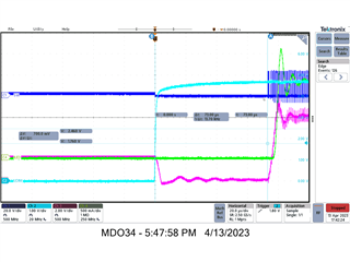
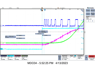
1. How long is the delay time when turning on and off with UDIM? Is it tUDIM(RISE)?  If so, please tell me Min and Max.

2. What is the delay time between devices when a signal is input to two ICs?

Best Regards,

  • Hello Kobayashi-san,

    Apologies for the delay as Friday was a holiday here in the US.

    I have assigned the pertinent engineer to help assist with your question. 

    Best,

    Pedro Arango Ramirez 

  • Hello Hirotsugu,

    It isn't clear to me how the second TPS92643 is powered from the first TPS92643.  This doesn't make any sense.  What are you trying to do?  The TPS92643 is a 3A constant current buck converter.  If each 642 is connected to the input and UDIM of each buck is connected together then the delays will be minimal.   

    Also, your diagram doesn't show the LED diodes connected to GND.  Please confirm if that is what was intended.

    -fhoude

  • Hi fhoude,

    Your diagram is correct.

    I want to align the emission timing of the two LED strings.

    So, I want to estimate the delay from the control signal.

  • Will you be doing PWM dimming or just use UDIM to enable channel?  

    The delay should be fairly short, but we do have a soft start sequence as the COMP capacitor is being charged up during the first pulse.  The delay is a function of the COMP capacitor value and the IADJ setpoint.  This only happens on the first UDIM pulse during PWM dimming.  Each subsequent pulse during PWM dimming starts immediately because the COMP capacitor is opened during the PWM OFF time, which means the COMP is left floating from the output of the Gm amp and then it starts up quickly and gets to it steady state operating point quickly.  

    This might be easier to answer if you just give me a requirement so that I can let you know if this will be an issue. 

    -fhoude

  • I understood a soft start sequence.

    It is simple if 5 LED's is be series configuration, but it is required boost converter.

    I want to design small size, so I selected buck converter included FET.

    But lighting timing difference between 2-strings is critical for our optical analysis, so I want to estimate delay time between IC's.
    The system is very long off time, I plan to use UDIM.
    Is there any other suggestion?

    Best Regards,

  • The initial soft-start for the converter can vary as a function of the capacitance used for COMP.  

    In this example we have approximately 73us.  

    Every subsequent UDIM high will have a much smaller delay because the COMP capacitor is charged and starts right up.  Delays are on the order of 230ns in this example circuit

    You can reduce the soft-start time by reducing COMP capacitance but there are limits there too.

    -Francis Houde

  • If you want something that reacts faster then you can use the LM3409 or the TPS92515.