Hi,
I am looking for IC for GFCI design for EV charger. I am looking for similar functionality as LM1851.
This thread has been locked.
If you have a related question, please click the "Ask a related question" button in the top right corner. The newly created question will be automatically linked to this question.
Hi,
I am looking for IC for GFCI design for EV charger. I am looking for similar functionality as LM1851.
Hello Himit,
I am looking this over and will respond shortly.
Sincerely,
Peter
Hello Himit,
The AFE3010 and LM1851 are similar in their end-functionality for UL 943 compliance. The AFE3010 uses digital logic to achieve the variable trip time vs. trip current relationship, noise filtering, neutral-to-ground detection, and auto-monitoring self-tests.
The AFE3010 is a single IC solution for UL 943 GFCI with auto-monitoring self tests.
Sincerely,
Peter
Hi Peter,
Thank you for your suggestion. Yes, I came across AFE3010 and its perfect for GFCI but I am looking for cheaper options with minimum components. I am looking for package which I can easily use for rework for my inhouse lab.
Hey Himit,
We do not have any other ground fault specific IC devices. You would need to develop a discrete circuit as seen below or pair the LM1851 (or something similar) with a microcontroller/processor to take care of any functionality, features, self-tests, etc that are required for you design.
https://www.ti.com/lit/ug/tidua56a/tidua56a.pdf
https://www.ti.com/lit/ug/tidua39a/tidua39a.pdf
https://www.ti.com/lit/ug/tiduf03/tiduf03.pdf
Hope this helps.
Best,
Peter
Hi Peter,
Thank you for your suggestion. While reading about this I came across term Zero phase current transformer. Does AFE3010 or any similar IC require Zero phase current transformer or they can work with normal transformer as ZCT is specially used for to detect leakage current.
Hello Himit,
No problem. The AFE3010 does not need a ZCT.
Please post back if you have any other questions.
Sincerely,
Peter
Hi Himit,
I saw that you were looking for a GFCI for EV Charging and wanted to highlight a reference design that may help for detecting both AC and DC fault currents utilizing a open loop fluxgate topology. The reference design I am referring to is TIDA-010237.
Best regards,
Errol
Hi Peter,
So it will work with any current transformer with required ratings, right?
Thanks,
Himit
Hey Himit,
The AFE3010 will work with any current transformer, although to get neutral-to-ground fault detection you need a second core with ~200 turns for the NGOUT pin to drive. And of course the CT should be voltage rated to specific application.
Sincerely,
Peter
Hi peter,
I have ordered Evaluation board for AFE3010 but I have few doubts for that.
1) I am not using solenoid for this EVM and we need to connect 10-15K resistor instead of solenoid. I am going to use heater as load with 120VAC 7A power rating. What is the power rating of this resistor for this application?
2) To check signal for SCR or OUT pins, I can use high voltage differential probe but is any high voltage differential probe fine for this? Can I use Micsig's DP10013 for this?
3) As per working functionality AFE3010, whenever there is fault, it will trigger the SCR. Now how will I differentiate between real fault and fault which is generated by self test pin? How can I apply this to my EV charger design?
4) For EV charger application I will drive 50A relay. Now I am thinking about connecting anode of SCR with my controller so when there is fault signal, SCR's anode will connect with cathode(here cathode is ground). I cant use this functionality as ground for AFE3010 is not common with board but it is floating. Can I use this signal to directly drive my relay? Can I connect SCR's pin output with controller(In this case ground of my controller and ground of AFE3010 is not common)?
5) Here we are generating supply for AFE3010 with bridge rectifier, instead of this can I connect supply(VDD) pin with DC voltage directly? if yes then what should be the range of this DC voltage? If I can use DC voltage for supply then it will solve my floating ground issue.
6) Do you have any other solution about how should I implement AFE3010 with my controller for EV charger to control the relay for leakage current?
Thank You,
Himit
Hello Himit,
1. The solenoid (or emulating resistor) is not dependent upon the load. The power rating of this resistor depends upon its resistance and if it can withstand up to two line cycles.
2. The probe you listed is rated to 1000V so this should be acceptable.
3. Any fault due to a self-test failure will result in a blinking ALARM pin, which is driving an LED.
4. You want to avoid connecting the AFE3010 to any ground-level IC directly. The AFE3010 when using the full bridge rectifier will have a floating, HV ground. So connecting this to any other IC or processor that does not have the same ground as AFE3010 will result in EOS damage.
You will want to find a way to isolate the signal from AFE3010 to any ground level IC whether by using an optocoupler or FETs.
Maybe it is possible to use an SCR trigger current to activate a relay, but 50A maybe too much for an SCR, also the ON time for SCR may not last much longer than a half-line cycle and thus may not be reliable for some relays.
5. Yes you can use a DC source, as long at it is >= 20V. You can use a higher voltage, but there will need to be current limiting resistors because this will be powering an internal 20-V, shunt regulator.
6. I would need more information about the relay. The AFE3010 can provide the signal, but more information is needed on will it drive an SCR long enough to activate the relay.
Sincerely,
Peter
Hi Peter,
Thank you for your response. I have some doubts according to your answers.
1. How can I calculate power rating for 10K resistor to withstand up to two line cycles? I have EVM, I just need this resistor before I turn it on, You can suggest me any recommended part as well according to my application.
2. I want to check signal even when test is successful so I can prove it's working functionality. It is generating fault signal every 3 seconds(180 cycles) for 60Hz signal. I can connect differential probe on SCR's pin on AFE3010 or connect it on anode of of SCR. I can check self test like this, other than the LED, right?
3. Here, I am using it for EV charger and how blinking LED will help me to differentiate between real fault and fault which is generated by self test pin? I am trying to add functionality like when SCR will trigger with fault signal or self test signal, I will use it for MCU or Relay but how will I know that is it real fault or fault due to self test? I just want to implement that when there is real fault, it will cut off power from relay but works perfectly fine when there is fault due to self test.
4. Now as you have mentioned in answer 5, I will use 20V DC so with this condition there is no floating ground, right? In this situation, can I use same ground for emitter of Q1 and capacitor(C8) used to connect PH pin?
5. I have 20V DC voltage for 20V, shunt regulator, even in this condition do I need to use current limiting resistor? If yes then it will have some voltage drop and then eventually, my voltage is less than 20V.
6. We are going to use HFE10-1/12-HT-L2.
Hey Himit,
1.I admit it is not exactly straight forward because it will be dependent upon the resistor's survivable peak current over one line cycle (16.7ms) and this may not be something easily available. Technically the average power over one line cycle for a 10kΩ is 120Vrms^2/10kΩ = 1.44W, but you won't need anything close to this because the SCR will not be on continuously. Personally I have used 1/8W, 10kΩ resistors without damaging the resistor. You could consider the average power for a PWM (16.67ms on and 300ms off), average power = (170 pk * SQRT(2*ton/toff))^2/10kΩ = 157mW.
2. You can check that system is working by simply turning the system on (connecting power) and observing that the ALARM LED blinks once 250ms after. To observe all functionality, you simply need to probe the following pins with respect to GND: OUT and SCR. Refer to the application curves in datasheet on what the signal should look like for working systems.
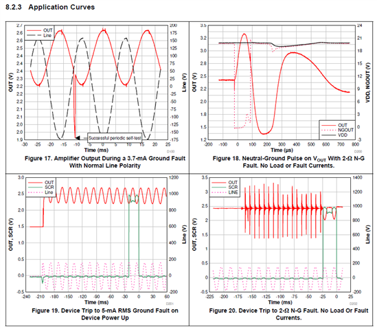
3. You would need logic (or processor/MCU) to make the determination of self-test/real fault and perform the action. The logic would be: real fault if ALARM is not blinking; self-test fail if ALARM is blinking. The device was made with an automatic firing of SCR for any self-test fail to adhere to the safe standards of the UL 943. If the system is overall failing and cannot sense real faults anymore then it is dangerous.
You can disable the SCR self-test by floating the SEL pin, but the periodic self-test (FT pin) and continuous self-test (watchdog timers for SCRTST and PH pins) cannot be disabled.
4. Yes, everything that is connected to ground in the typical application circuit still must remain connected to AFE3010 ground.
5. If your external source is 20V, then you don't need the current-limiting resistors into VDD pin.
6. This relay probably cannot be safely activate directly by the SCR pin alone. The datasheet shows a 50ms minimum pulse duration. The SCR may only drive the relay for 1 line cycle (16.67 ms). Also, the nominal coil voltage is 12V. The SCR pin cannot go higher than 5V. You would need to create another stage to that drive relay coil to 12V for minimum 50ms upon being activated by the SCR signal.
Sincerely,
Peter
Hi Peter,
Thank so much for all the answers. Please find my updated comments according to your answer.
1. Just for the safe side, I am thinking about using ten 100k resistors with 250mW power rating(easily available for me for inhouse testing) in parallel so eventually it is 10K and 2.5W. Can I use combination like this?
2. Sure I will check and update you if I have any concerns.
3. As per datasheet, AFE3010 will trigger SCR for both real fault or fault caused by self test. Now for LED blinking, which I can connect directly with MCU, will be low if self test passes and it will be blinking if self test fails. What will be its status in real fault? You mentioned that real fault if alarm is not blinking but it is not blinking even when the self test passes. I still don't understand that how should I differentiate between real fault and fault caused by self test.
Let me explain, what I am think about how I am going to use AFE3010 to detect ground fault and control relay for my EV charger. I will connect anode of SCR with my MCU(I will use optocoupler to make both grounds common), now when there is fault, it will trigger my SCR and anode will connect with ground. As this pin is connected with MCU, it will detect the fault and I can control relay with MCU(In this situation I still dont know how to differentiate between real fault or fault caused by self test). Please let me know if you have any other suggestion for this.
Hey Himit,
1. Yes you can do this, but I think you will observe that these resistors barely feel any warmer when device has fired SCR.
3. The logic is this: If MCU sees SCR fired and ALARM not blinking, then there was a real fault. If MCU see SCR is fired and ALARM is blinking, then AFE3010 detected an End-of-Life (EOL) condition (thus fails self test). Thus to determine the different status, you may need to monitor the SCR pin as well.
So you should not need an actual SCR component if you are using the relay to open the switch. I suppose you can use the SCR to pull high current through the relay coils, but this would need to be validated especially given the 50ms minimum pulse duration time for relay. Keep in mind the standard you will have to pass, 50ms is too long for UL 943high current faults, although I am not certain about what standards/regulations you are trying to satisfy.
As for the MCU monitoring all of this, I would think it would be easier for MCU to monitor the SCR pin as opposed to the SCR anode. The SCR anode will be oscillating quite a bit and there could be some non-linearities here the MCU firmware would have to ignore. If MCU can simply sense SCR, then the trigger is simply when SCR ~> 1V for ~>5ms.
Sincerely,
Peter
Hi Peter,
I have tested AFE3010EVM and it is working fine as per expectation. LED is blinking once when I power on and then it is off. Even I have checked SCR signal with differential probe and it is around 50-60 mV and I am using 50x attenuation so it is around 2.5-3 V.
1) Sorry to ask you again but I am still not clear how can we differentiate between real fault and fault which is generated by self test pin. I know when SCR is high and LED is blinking then self test is failing so We will discuss about only 2 condition.
1. Real fault : In this situation SCR is high until there is leakage current. In this situation Alarm pin low.
2. Fault generated by self-test : In this situation SCR is high for few milliseconds when there is fault signal by FT pin. In this situation Alarm pin low.
In both these situations SCR pin is high so how will I know that is it real fault or not?
2) I am going to order AFE3010 IC only and design similar circuit on general purpose board, what do I need to take care while doing this?
3) Now I want to implement this design for 240VAC and 40A for level 2 AC EV charger, which components should I change? Do have have details for current transformer?
4) Do you have any suggestion about how can I use optocoupler to separate both grounds and use SCR signal directly with MCU pin?
5) How can I use PTT pin to test the circuit?
Thank you,
Himit
Hi Peter,
I have one more question. I will order AFE3010 and will solder it on general purpose board which has 16 pin QFN package but I dont have die pad on that general purpose PCB, will it create any issue? I know die pad is ground and it should be connected with ground pin internally.
Thank You,
Himit
Hello Himit,
1.
Real Fault: SCR goes high for ~1 line cycle.
Self-test Failt: SCR goes high for ~1 line cycle and ALARM starts blinking one every second.
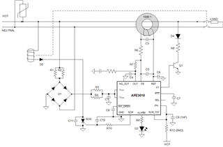
2. You need to essentially recreate the AFE3010EVM. If you don't need neutral-to-ground detection, then you don't need the 200 turn coil and you can float NGOUT pin. If you don't need the SCR self-test, then you can float the SEL pin and short SCRTST and PH pins together. Thus it would look like this:
3. For 240VAC, you will need to adjust some components. I have attached a calculator on how to adjust component power values for 240VAC.
4. I am not proficient with optocouplers, but it should be possible to translate the signal over and isolate the grounds of AFE3010 and MCU.
5. You can use PTT or SWOPEN pins to test circuit. You can use a simple normally-open switch to pull either pin low. Refer to Figures 11-14 on how device will respond when toggling these pins.
As for the thermal pad, it is not necessary to have connected to ground for general prototyping, but it should be connected to ground for any system validation as this is how the device was tested and characterized and is best practice for the package.
Sincerely,
Peter
Hi Peter,
Thank you so much for the support you are providing to me. I really appreciate that.
1.
Real Fault: SCR goes high for ~1 line cycle.
Self-test Fail : SCR goes high for ~1 line cycle and ALARM starts blinking one every second.
Self-test Pass : ? (Isn't it similar to Real fault?)
2. Yes, I don't need both tests now so will follow your suggestion.
3. Now as per the calculator sheet I understood that I need to change values for R1, R2, R3, R4 , R11 and R8. I will follow recommended values for R9,C3, Rs and Cs from this sheet. Everything else in the design will remain same, right?
Can I use CR8420-1000-G instead of current transformer as I don't need ground neutral fault?
Now for calculation of R1, R2, R3, R4 , R11 and R8, I have some doubts.
R1, R2, R3, R4 Calculation : For this I need higher power and/or higher resistance, what is the highest resistance value can I use? As per power calculation sheet, peak power will be 2.310W so finding these high power resistor in smaller size for EV charger is difficult task. Can I use 3-4 resistors in parallel to make it equivalent resistance with higher power? Do you have any other solution for this?
R11 : As I am not using SCR test, I don't need this resistor.
R8 calculation : Here Q1 maximum power dissipation is 80W and peak power is increased by 4 times for 240VAC compare to 120VAC. In EVM R8 value is 10.5K, 0.75W. As per R8-Q1 collector resistor power calculation how to check power only for resistor by using same transistor? Will 10.5K,1.5W be enough?
4. I will connect AFE3010 without die pad and will let you know if I have any issue.
Thank You,
Himit
Hello Himit,
1. For any self-test pass (periodic or continuous), the device does nothing and remains in a ready mode (ready to trip to a real fault). The only time the device performs an action after a self-test pass is when you activate the PTT or SWOPEN pins (see Figures 11 through 14).
3. Yes when adjusting for higher line voltages, you only need to change R1, R2, R3, R4, R8, R11, and R12. Of course, also make sure any capacitors on line have correct voltage ratings.
For the input, current-limiting resistors at VDD, yes you can add more resistors in parallel with R1||R2 and R3||R4 in order to use lower power rated resistors. The tradeoff here is PCB space vs. resistor power rating. The spreadsheet I attached in last thread actually includes a tab to calculate required resistance for 3 parallel resistors (as opposed to the typical 2).
Keep in mind that the main limiting factor for these resistors is the UL 943 Section 6.31 c) requirement where the system must remain operational even if one of these resistors were to experience an open failure condition. I provide what the power should be given this worst-case condition in Cells D36 or G36, choose whichever is reference back to 240VAC. Of course please refer to the standard and regulation you are trying to comply with. Maybe the requirements for your system standard differ from UL 943.
For example, in the typical 2 parallel resistor (R1||R2 and R3||R4), for 240VAC line and 18kΩ resistors, each resistor would need a power rating of at least 0.706W; however, if one of the resistors were to fail and open, then each resistor should be rated to at least 1.255 W for system to remain operational.
If you change the line voltage to 240VAC (assume 276 VAC max; +15% variation) and add a third parallel resistors (R1||R2||R13 and R3||R4||R14), then you should first increase the resistance of each resistor to anywhere in between 20kΩ to 28kΩ each. If we choose R=26kΩ, then each resistor need at least 0.657W power rating; however, if one of these resistors were to fail and open, then each resistor should be rated to at least 0.946W.
All of these number, I determined using the aforementioned calculator I sent you.
For R11, yes you do not need this, but you should short SCRTST to PH.
For R12, you would need to either double the resistance or power rating for 240VAC, but since PH and SCRTST are shorted together, you would need to double either the resistance or power again because you are doubling the leakage through R12.
R8 should be a relatively low power resistor. The worst-case condition is when there is really a fault condition and FR will be turning on Q1 for one cycle every 60 cycles (1 second for 60Hz line) and repeat this 5 times (5 seconds for 60Hz line). After the 5th consecutive self-FT fail, the device will make determination there is a failure condition and thus fire SCR and blink ALARM. In the calculator, I calculate average power, by calculating RMS voltage drop across R8 for Q1 on for one cycle and off for the rest during a one second timeframe. For a line operating exclusively at 240VAC, you can either double R8 or double R8's power rating. So for R8 = 20.9kΩ and line = 240VAC, the required power rating for R8 is 0.09W so any resistor > 0.25W should be very robust.
Hope this all makes sense. Please let me know how else I can finalize your prototype design.
Sincerely,
Peter
Hello Peter,
Thank you so much for your response and support.
I am going through your answers and will let you know if I have any doubt.
Meanwhile I have one question like I have used AC1050 current transformer but is there anything like primary and secondary winding connection for FB and REF pins?
Hi Peter,
Please find my below questions as per your answer.
1. Sorry for this question again but PTT and SWOPEN pins are active low for sometime as per figure 11-14. Its like we are keeping these pins low. How will these pins behave in relay fault?
What I want to achieve is, I will connect SCR pin with MCU and I will consider it as real fault when SCR ~> 1V for ~>5ms. From this I will control relay and cut-off the power. Now SCR pin state is same for both real fault and self test fault. Which other pins behaves differently to differentiate between real fault and self test fault?
Real fault -
SCR - High for few ms.
Alarm - Low
PTT - ?
SWOPEN - ?
Fault due to self test -
SCR - High for few ms.
Alarm - Low
PTT - ?
SWOPEN - ?
3. For Capacitors 250VAC, Same as EVM is fine, right? In EVM we have max 120VAC and in my design we have Line 1 and Line 2. Voltage across Line 1 or 2 with respect to ground is 120VAC. If I check between them then it is 240VAC. Here we have used capacitors with Line 1 or 2 but not between 2 Lines so I feel voltage ratings for capacitors are ok. Correct me if I am wrong.
4. I have one question like I have used AC1050 current transformer but is there anything like primary and secondary winding connection for FB and REF pins? Is it okay to use this current transformer?
For everything else I will follow your recommendation and complete prototype design and compare its results with EVM.
Thank You,
Himit
Hello Himit,
1. PTT and SWOPEN do not do anything during a fault or self-test pass. They are digital input pins should be driven/controlled by user (via pressing a normally open button) or MCU GPIO pulling the pins low.
Your description of ALARM during a fault due to self test seems incorrect. Once device determines it is failing its periodic/continuous self test, SCR is fired and ALARM starts blinking at 0.5Hz (1 second off, 1 second on, where the ON time is the ALARM voltage pulse-width modulating going from GND to ~5V at 3kHz, 50% duty cycle).
Thus the only way for your MCU to determine that SCR is firing (active high) due to a failing self-test is to wait up to 1 second and check if ALARM is going high. This is not a safe method if your MCU is waiting this long while a real fault is occurring.
3. The capacitor should be rated to the voltage fed into the bridge rectifier. So if your rectifier inputs are Line1 and Neutral, then the 120VAC should be fine. Are Line1 and Line2 in phase? When working with multiple phase systems, you may need to consider that you might need an AFE3010 circuit for each line. The AFE3010 sense the differential current from a current transformer and this differential current needs to be in phase with the line voltage is clocking from (the internal clock is set by the zero-crossing transition sensed by Phase (PH) pin.
4. The AC1050 seems to be a perfectly fine current transformer to use with AFE301 as shown in the AFE3010 typical recommended schematic
Sounds very good. I look forward to your results.
Sincerely,
Peter
Hi Peter,
I have completed the prototype but it is failing the self test. LED is blinking in 1 second interval after around 5-10 seconds of power up. I have checked all connection and everything as it looks fine to me. I have attached schematic about my connections.
Let me update you about few things as per this schematic.
1. First I am trying to implement it for 120VAC and once it is tested on 120VAC, I will check it on 240VAC.
2. For R1, R2, R3 and R4, I have used eleven 100K resistors in parallel so eventually overall resistance is 9.09K for both pairs.
3. In place of solenoid, I have used ten 100K resistors between line and anode of D2 and it is same as EVM for me.
4. I have not used C11 because it is no load in EVM as well.
5. For R12 I have used two 2M resistors in parallel as I want to check its functionality on 120VAC first.
6. For R8 I have used 43K, 43K and 20K resistors in parallel so eventually it is 10.36K I want to check its functionality on 120VAC.
7. For C3, I have used 680nF capacitor.
8.NG_OUT and SEL pins are floating in this design.
9. I have connected 2 pins of AC1050 current transformer across C3 capacitor. In this design I have not taken care about which current transformer pin should be connected with FB or REF pin. I hope it is fine. AC1050 has 3 pins but as 3rd pin is for support only, I have used 2 pins.
For debug steps as per EVM datasheet, I have checked first 6 steps and everything is ok in that. I will check OUT and FT pin with differential probe next.
Do you have any other suggestion for this debug?
Thank you,
Himit
Hi Peter,
One more thing with this. I have not connected any load with this. Will it affect working functionality of AFE3010?
Thank you,
Himit
Hey Himit,
No. The presence of a load does not matter to AFE3010 operation.
It could be either that the Vout signal is in phase with HOT-Neutral, or the feedback gain (set by R7) is not high enough.
I recommend using high-voltage differential probes to probe OUT-GND and LINE (HOT-Neutral) and see if you can get it to match Figure 17 except where OUT does not have any sinusoid component, but rather is a flat line at ~2.5V with a downward pulse that occurs every 3 seconds. Use a falling edge trigger at <2.3V on Vout to catch this. It should be pretty apparent.
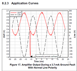
What is happening is that the device cannot see this downward pulse at 1 second after power and thus it repeats the test every second until it fails 5 consecutive time. Once this happens it fires SCR and blinks ALARM.
If signals are in phase, then make sure PH is connected to HOT. If it is, then reverse the CT coil connections to the AFE3010. If signal are out of phase by ~180 (which is what you want), then increase R7 until you see Vout glitch get to ~1.9V and system stops failing self-fault test.
Note that there could be a chance the Q1 you have selected does not have a high enough beta and thus is not really pulling enough current, which could be why device is not seeing this fault. You will realize this if once you correct your system, you see device does not trip at 5mArms, but rather something higher. Which means you would have to decrease gain (decrease R7). If the fault re-appears, consider changing Q1 or reducing R8 until device stops failing self fault test.
Sincerely,
Peter
Hi Peter,
I have done some changes as per your suggestion but still I have few doubts
1. I have checked out signal with differential probe on falling edge but there is no signal(like 0V) on that. Due to this I have checked same functionality with EVM as well but in EVM there is no signal(like 0V) on OUT pin. I am not able to check OUT-GND and LINE (HOT-Neutral) at the same time as I have only 1 differential probe. With this how can I check OUT signal in EVM as well in my prototype.
2. You have mentioned that OUT pin should be out of phase for correct operation but you have also mentioned that OUT pin is flat line around 2.5V then how should I know if it is in phase our out of phase?
3. I have changed current transformer connection but still the result is same. For AC1050 they have mentioned Pin 3: Normally for mechanical support only but will be used on center tapped designs. Will this create any issue?
4. As I have solder AFE3010 inhouse, it may possible that dry solder for any pin. I have observed it with magnifier and also checked it with DMM and it looks okay to me. Do you have any suggestion how can I verify this?
5. As I dont have enough data that why this is failing, I dont know should I increase or decrease values for R7 and R8 but I will change it today to nearby values and see how it behaves.
Thank You,
Himit
Hi Peter,
I have few updated after my further testing.
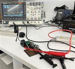
1. I am able to check signal on OUT for EVM and my prototype, the only difference is that in EVM there is downward pulse but in my prototype there is none. I have checked this again by swapping the pins for current transformer but still the result is same. As I don't know my system is in-phase or out of phase but still as per you suggestion I just tried to increase the value of R7 to 39K and check again. From this point LED on prototype board is not functioning at all. I have also attached one image to show how out signal looks like in this stage. I tried to reduce R7 to 36K but still the result of LED and pulse on OUT pin is same.
Why this is happening? What should I do next?
Thank you,
Himit

Hey Himit,
It’s a problem that your OIT signal is not becoming close to 2.5V bias point.
Can you try measuring VDD to make sure it’s at 20 V?
If VDD is good, then there could be a loading issue on amplifier. Try lowering the the coil capacitor from 620 nF to smaller value down to 100nF to see if this stabilizes it.
To check if it’s a solder error you could try to fly wire your transformer to the EVM, but keep in mind you can’t have both of these transformers connected at same time. The EVM has single socket connectors that could make it easy to do this.
Sincerely,
Peter
Hi Peter,
In previous board, due to some reason the AFE3010 got damaged so I have removed it and add new one so it is working same as previous board(LED is Blinking after 5 seconds).
Now I am focusing on solving this self test fail issue. For that I have few doubts.
1. You have mentioned that OUT pin should be out of phase for correct operation but you have also mentioned that OUT pin is flat line around 2.5V then how should I know if it is in phase our out of phase?
2. I have changed current transformer connection but still the result is same. For AC1050 they have mentioned Pin 3: Normally for mechanical support only but will be used on center tapped designs. Will this create any issue?
3. As I am not getting downward pulse on OUT pin, I am going to increase R7 value but how much should I increase(I just want to confirm because while doing this change the AFE3010 got damaged)?
I am doing changes as you have suggested in previous comments and will update you the result.
Thank you,
Himit
Hi Peter,
With above questions I have few more questions.
1. We are going to use this for 2 phase system with Line 1 and Line 2. Voltage between Line 1 and PE is 120VAC. Voltage between Line 2 and PE is 120VAC. Voltage between Line 1 and Line 2 is 240VAC. As per my understanding return path for Line 1 is Line 2 so I think I need to use only 1 AFE3010 to detect the leakage current, right? As per me this is in phase system so 120VAC is adding to 120VAC and making it 240VAC. Is there anything I am missing here?
2. Now to differentiate between real test and fault test, I still dont know how we are going to do it. What I want to achieve is like when there is real fault MCU can differentiate it with self test fault and control the relay within required time period as per UL standard. Do you have any suggestion for this?
3. I go ahead and updated R7 to 36.5K, 37K, 37.5K and 38K but still I am only getting signal around 2.5V without downward pulse. I have also swapped current transformer pins but still it is same. How can I control R7 or R8 to make this work?
Thank You,
Himit
Hey Himit,
Before any more debugging, please make the following system-level changes to your circuit:
1. Connect only LINE1 and PE to the full-bridge rectifier (D1), at least until you have stable operation. So LINE2 should have no connection or interaction with your current circuit.
2. Feed only LINE1 and the PE cables through the current transformer.
Basically you need to replace LINE2 with PE in your current schematic.
Given that LINE1 and LINE2 are out of phase, connecting both the D1 this could be impacting the operation of the device. It will be much more difficult to debug this if we do not make this change. While yes, the AFE3010 will sense differential fault current, the leakage path could go from LINE1 to PE and thus would not be sensed if you are only feeding through LINE1 and LINE2 through the CT. There is a chance you may need two AFE3010 circuits to measure fault for LINE1 to PE and LINE2 to PE. The AFE3010 was designed to work with single phase (HOT and NEUTRAL) systems.
Once you have done, this repeat a power up test and observe the behavior. I will assume the behavior remains the same.
1. Yes, any V_OUT sinusoid (due to a resistive leakage) should be ~180° out of phase with LINE1. Sorry I did not clarify this. The out-of-phase AC component of V_OUT is due to a real resistive leakage fault from LINE1 to Earth ground. Thus the only way to confirm this is to place a resistive fault to ground at the load terminals of your prototype.
2. You should not need to use pin3 of the CT.
3. Before increasing R7, please make the system-level changes I recommended above. Also confirm Q1 is turning on during the self FT. You can probe across R8 or Q1 to see if Q1 is fully turning on.
Once again, try probing VDD to make sure it is stable at 20-V
Hope this helps.
Sincerely,
Peter
Hi Peter,
1. As of now I am connecting everything with 120VAC(Line and Neutral) and all the values in my design are according to that. 2 phase, 240VAC, I am discussing is next plan of action, once we are done with successful testing on 120VAC.
I am focusing on solving the issue for 120VAC now so we will discuss about 2 phase system after the successful testing.
1. What kind of resistive fault I can use? I have only one differential probe so how can I check 2 signals to verify, is it in phase or out of phase?
3. As the circuit I am using is already according to what you have suggested(Only thing I dont know is that if it is in phase or out of phase so I have swapped current transformer pins when I am increasing R7 but still it is same) and I have tried highest 43K and lowest 34.5K but I am only getting 2.5V signal without downward signal. As you have suggested, once I increase/decrease R7, voltage on OUT pin should reach around 1.9V, right?
Q1 is working turning on but is on for more period compare to EVM. Same to this the FT pin signal is also stay high for more period compare to EVM. Is this period more for first 5 seconds? Please find attached images for understanding.


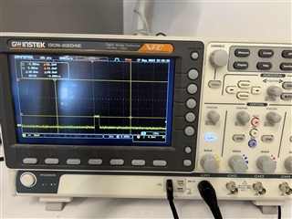

Hello Himit,
I will say it is going to be difficult to debug the setup with only one high-voltage differential probe, especially when trying to determine if CT polarity is correct.
So it is clear that the device cannot pass its self fault test via the FT pin, so either the polarity is wrong, the system gain is too low, or there is some other pin not connected properly
Please probe each of the following pins starting at power up:
OUT pin with respect to GND
VDD pin with respect to GND
Sincerely,
Peter
Hi Peter,
Thank you for your update.
Please find below details as per my current testing. We have ordered 2nd differential probe and we will receive it shortly.
1. FT pin is on for around 2ms in EVM and around 7ms for our prototype. Due to this Q1 is on for same amount of time. As per my understanding FT pin generates fault test signal internally then why this time is different for EVM and prototype. I have attached images for all these signals with proper name for your understanding.
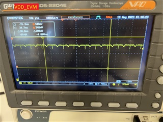
2. I am also attaching VDD signal for both EVM and prototype.
3. I have ordered same npn transistor as EVM and check result but it is same as before.
4. Just to make everything same as EVM I connected SEL pin with ground and connected SCR_TST pin with anode of SCR with 51K resistor. In this testing, LED starts blinking as soon as I power up the device.
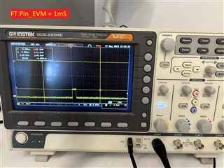



Hey Himit,
It is good that your VDD is stable.
The AFE3010 is failing its self fault test. That is why the FT pin is driving the entire half line cycle. The root cause for this failure is that the amplifier is not sensing a large enough fault signal.
Would you please probe the following signals right after powers up for about 200 ms timeframe?
OUT to GND
PH and HOT to GND.
Sincerely,
Peter
Hi Peter,
Thank you for your support throughout this period. I have used op-amp to make gfci circuit and it is working completely fine.
Thank you,
Himit