This thread has been locked.

If you have a related question, please click the "Ask a related question" button in the top right corner. The newly created question will be automatically linked to this question.

LM5116: LM5116 does not work as expected. Vout value is not correct.

Part Number: LM5116

Hello experts!

I have designed a buck converter to reduce an input voltage of 24-60VDC to an output of 12VDC . I have used the WEBENCH tool, recommended in the datasheet.

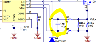
You can see the circuit in the following image:

I have also simulated the circuit with PSPICE for TI, using the values given by WEBENCH, and the output is correct (12VDC).

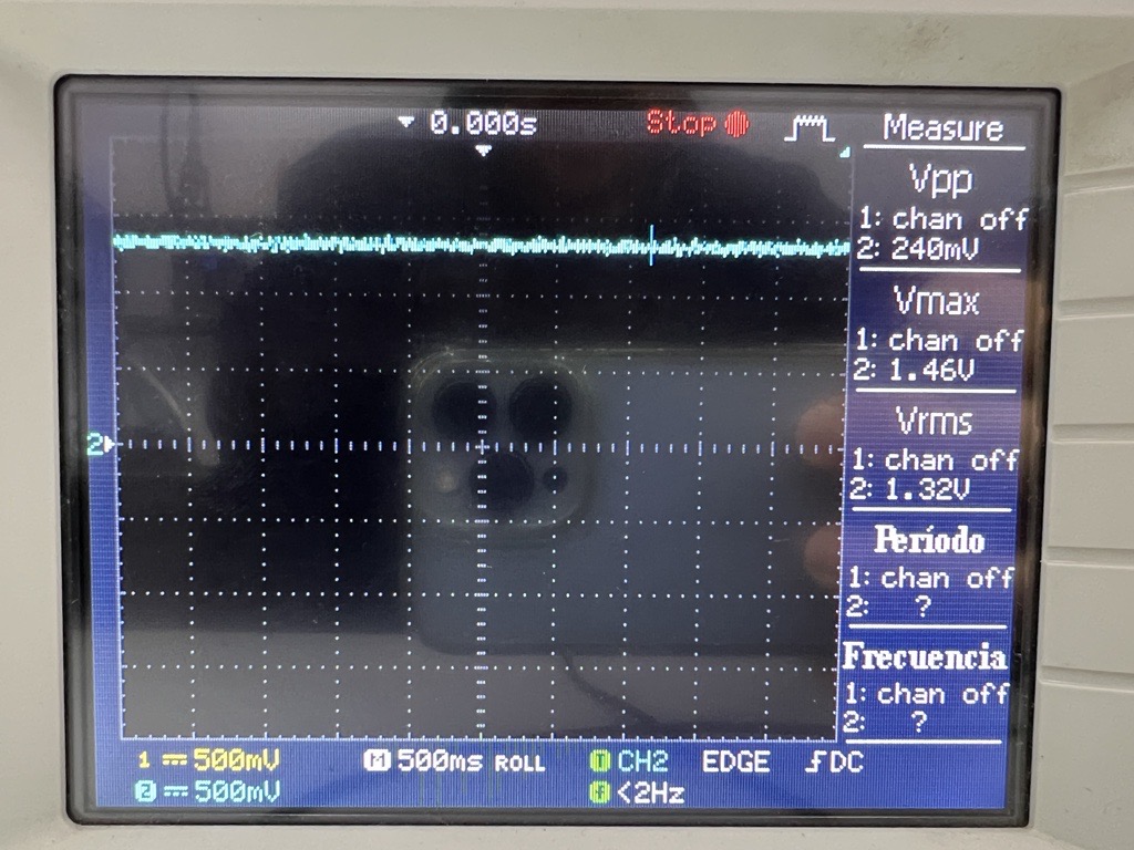
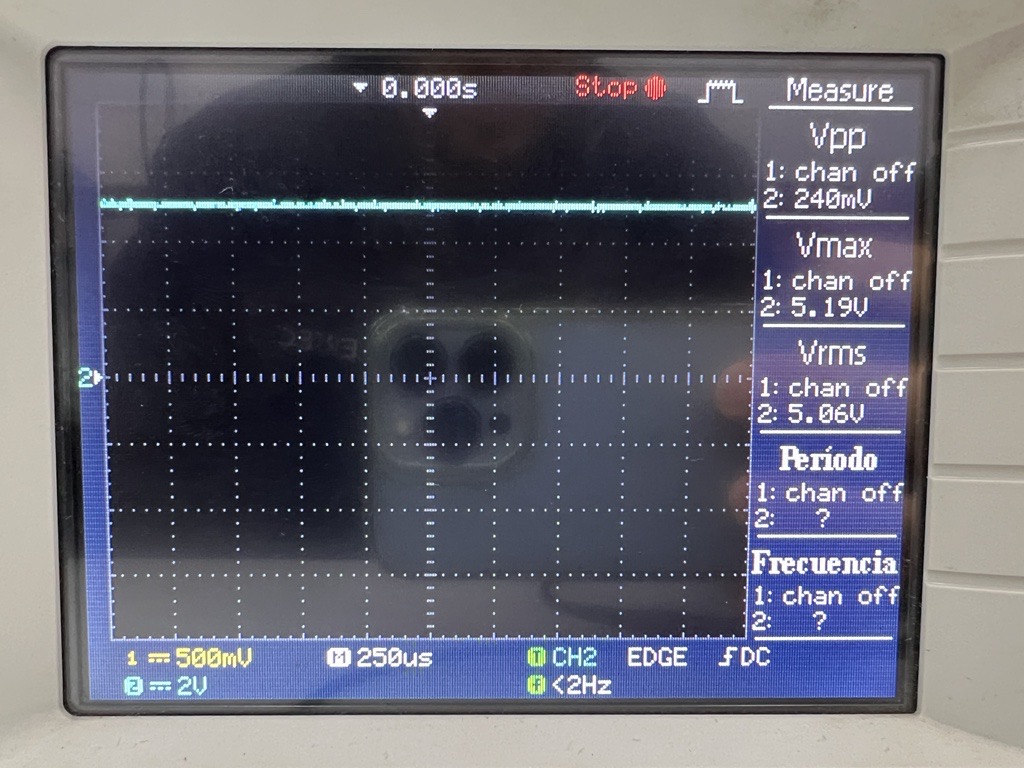
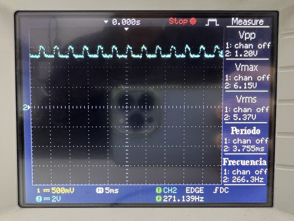
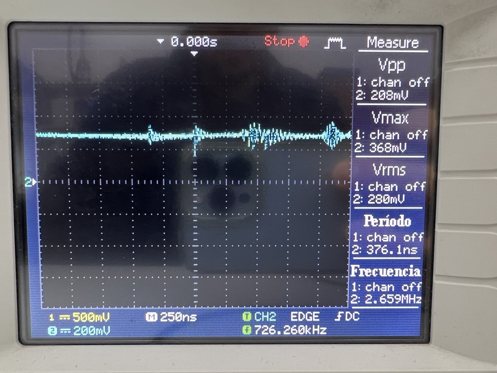
I decided to order the designed PCB from an external company, and once I had it, I tested it. All the pins of the LM5116 are apparently working correctly (by checking voltage with a multimeter), except for the HO and the LO pins. As these pins are not working properly, the mosfets are not  working properly. I tried soldering more capacitors on the inputs and output but Vout does not change (-300mV). Then I changed the resistor Rt to change the frequency, and the output changed to 100mV, but it is still far away from the 12VDC that I want. I am using an input voltage of 30VDC to test it.

Can you give me some idea of what is wrong and understand why it is not working properly?

  • Hello Pablo

    Would you please check these items step by step using oscilloscope?

    1. The UVLO and EN pin voltages are greater than the threshold ?
    2. VCC is in regulation ?   
    3. SS is ramping up ?
    4. COMP is ramping up ? 
    5. V(HB-SW) is close to the VCC voltage ? 
    6. HO is electrically connected to the gate of the high-side MOSFET  ? ==> Use DVM
    7. LO is electrically connected to the gate of the high-side MOSFET ? ==> Use DVM 

    -EL

  • Hello, thank you so much for your answer! I attach the oscilloscope images:

    1) UVLO: (1.32V)

    EN: (5.06V)

    2) Vcc: (5.37V)

    3) SS: It looks like it is not ramping up correctly.

    4) COMP: (4.79V)

    5) HB: (1.48V)

    SW: (-400mV) It should be 12V, like Vout.

    HB - SW = 1.9V.

    Vcc = 5.37V.

    6) HO: HO is correctly connected to the gate of the high-side MOSFET

    7) LO: LO is correctly connected to the gate of the low-side MOSFET

  • Hello Pablo 

    Something is totally wrong now. It might be caused by a wrong layout or  a wrong component population. And also there is a possibility the device is already damaged. 

    • VCC should be around 7.4V 
    • SS should ramp up. 
    • HB should be at least the same as VIN voltage(even if the device is not working.
    • SW should be close to VOUT. Since the VOUT is ~ 0V. SW should be ~ 0V. 

    Please check these items step by step. 

    1. Review your schematic 
    2. Review layout 
    3. Double check the component values and directions 
    4. Replace the IC  
    5. Power on and check the VIN pin voltage

    Especially, please check if the HB diode is damaged. 

    - EL

  • Hello, finally everything is ok. The HB diode was damaged. With the new diode everything works fine.

    Thank you!

  • Thanks for choosing TI. Please feel free to contact us if you have any question.
    -EL

  • Hello! Everything is fine now, but I would like to ask a question, because the LM5116 is not working as expected.

    I am using a programmable electronic load to test the LM5116. I have designed the PCB for 120W (Pout), 12V (Vout) and 10A (Iout).

    When I increase the load from 0A to 5A, the LM5116 works perfectly. Vout is 12V and 60W with 5A.

    The problem occurs when I increase the load (e.g. 5.5A). The LM5116 does not work as planned and Vout drops to 3.8V. I have discard a temperature problem.

    I was checking the datasheet, but I can not solve the situation. Can you give me some idea of what is not working correctly?

    Thank you!

  • Hello Pablo

    If you are using the same component values as the WEBENCH recommendations, I guess  there is a noise injection to CS-CSG and the current limit is being triggered now. Please check if any improvement by reducing the current sense resistor value. 

    - EL  

  • Hello! I have tried reducing the current sense resistor value, but it still does not work as planned. The Vout drops even earlier with the smaller resistor (3mohms instead of 5mohms).

  • Hello Pablo

    Then, please double check the current limit of your power supply and check if any voltage drop at VIN when you increase the load. 

    Also, please try to populate 100pF between CS-CSG close to the IC. 

    -EL

  • Hello!

    There is no problem with the current limit of the power supply because it is 10A. Vin does not drop when I increase the load. I tried with the capacitor between CS-CSG, but Vout still drops when the load exceeds 5A (60W). I do not know why this happens, because everything is as webench says, and it works perfectly within 0.1A-5A. But it should work up to 10A.

    Thank you!

  • Hello Pablo 

    Would you please download Quick-Start calculator at https://www.ti.com/lit/zip/snvu051, and double check your component selections while checking if any wrong component populated ?   

    -EL

  • Hello Eric, I downloaded this calculator before designing the PCB to double check before manufacturing it. All the components are checked, everything is as WEBENCH and the calculator indicates.

    Thank you!

  • Hello Pablo 

    Since you confirmed there is no issue on your test set ups and your design matches with Quick Start and WEBENCH calculations, I guess there might be an issue on the PCB layout.

    -EL

  • Hello Eric!

    I have been checking the layout, and everything seems to be fine. I have used a different power supply, another fan to cool the PCB, and I reach an output power of 100W, but with some problems that I would like to solve:

    - When I reach 100W (attached photo), the output voltage drops after 4-6 seconds (below 8V).

    - The maximum stable power is about 75W.

    - When the output voltage drops, I have to decrease the load a lot to make the system stable again. Maybe with 4-5A I can recover the 12V output.

    - The 100W are reached with an input voltage of 26-28V. When the voltage is lower (24V) or higher (30V), the maximum output power is lower. I designed the system to works within 20V and 60V, so it should not vary.

    Thank you!

  • Hello Pablo 

    Since there is no circuit/component which has 4 -6 seconds time constant, I believe this issue is caused by temperature, if you have IR camera. please check the component temperature while increasing the load gradually. Especially, please check the temperature of IC, MOSFETs and sense resistor. 

    -EL