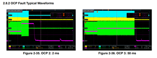
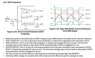
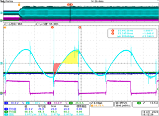
Figure 1 shows OCP3 operating waveforms. Figure 2 shows OCP3 not working.
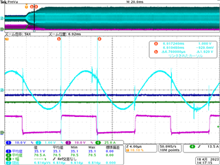
The ISNS pin (ch2) in Fig. 1 has an average value of 0.403V per cycle, so it corresponds to "OCP3 threshold min 0.40V".
Figure 2 is also 0.449V, so it should correspond to "OCP3 threshold min 0.40V". However, Figure 2 does not show OCP3 operation.
In addition, the operation to pull out the FB terminal from another circuit is implemented.
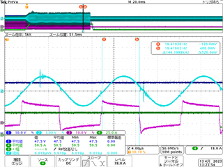
fig.1
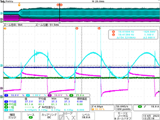
fig.2
ch1: output voltage ch2: ISNS pin voltage ch3: HO pin voltage ch4: output current
thank you.