

Hi,
I would like to ask question on the capability of TPS54310 for driving DC motors.
I adopted TPS54310 from Spectrum Digital’s DM6437 EVM board to my customized board. It works very well in supplying power to DSP as well as other ICs. However, currently I am planning to integrate a motor into the system, so I would like to ask about the capability of TPS54310 on driving motors.
I looked at maximum rating and parameters of TPS54310 in slvs412d:
1. It is labeled as “3-V TO 6-V INPUT, 3-A OUTPUT SYNCHRONOUS-BUCK PWM SWITCHER WITH INTEGRATED FETs”, and is featured as “60-mΩ MOSFET Switches for High Efficiency at 3-A Continuous Output Source or Sink Current”.
Does this mean it is capable of output 3-A current continuously as long as the voltage is within the range?
2. What if there is a sudden switch of the motor? For example, some stepper motor has current of 1A, and if I use an H-drive or transistor to suddenly turn the motor on, there is immediately a 1A increase of current. If I supply 3.3V voltage to the motor, and the 3.3V is also shared by I/O pins of DSP and other ICs, would this sudden 1A current increase interfere with the supply of the I/O pins? Would this cause the 3.3V voltage to decrease temporarily? Would this cause decrease of the current that are flowing through the I/O pins?
3. In addition to 3.3V example above, there are also 1.05V / 1.8V / 5V power supply on the board, and both {1.05V / 1.8V } are supplied by TPS54310. In particular, 1.05V supplies the core voltage of DSP and 1.8V supplies the DDR2 memory and much of the remaining of the DSP. If I am connecting a motor to these voltage outputs, and assuming the maximum current through the motor be less than 1A, would they disrupt the working of DSP and DDR2? How severe can this be?
4. On page 4 of slvs412d I read the following
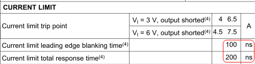
What does “leading edge blanking time” and “total response time” refer to? Do they have any similarity to the concept of “rise time” in chip’s timing characteristics? From a macroscopic perspective, these 100ns and 200ns time are quite small, but since a 500MHz chip has clock cycle of only 2ns, and 100-200ns are dozens or hundreds of times larger than chip’s cycle time, would they have any negative impact on running of the chip?
5. So far my questions all revolve around the current supplying capability of TPS54310. However, it is the battery (in a mobile device) that ultimately supplies current to TPS54310, then to ICs, motor as well as other devices. So are questions (1) (2) (3) (4) more relevant to battery’s capability/parameter rather than to TPS54310, or they both need to be considered?
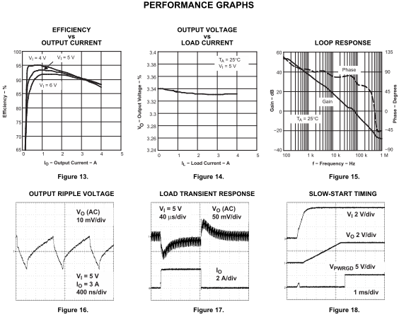
I also found “Performance Graphs” on page 11 of slvs412d and it seems to me that many of the questions above and find at least partial answers in the graphs. However, I lack the necessary knowledge to understand these graphs, particularly
1.Figure 15
2.Figure 16
3.Figure 17
4.Figure 18
Could anyone explain briefly the meaning of these four figures?
Zheng