This thread has been locked.

If you have a related question, please click the "Ask a related question" button in the top right corner. The newly created question will be automatically linked to this question.

LM5036: abnormal SR behavior

Part Number: LM5036

Hello

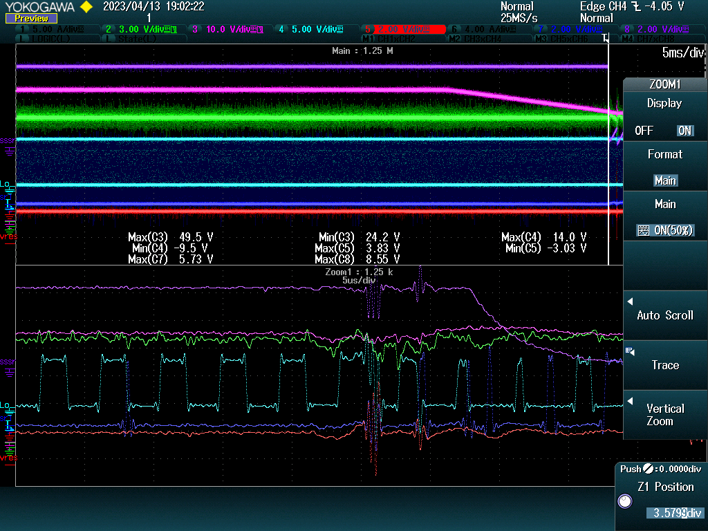
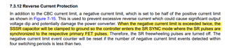
Our application is DC/DC converter, topology is half bridge and the input is 48V,  we observed abnormal behavior during on/off test with LM5036, see below. 

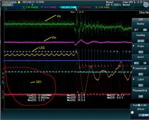
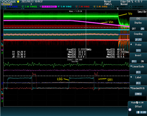
at normal conditions, the SR1 is complement to LSG. 

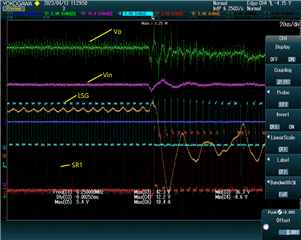
but sometimes we observe the SR1 is lost or operates at minimum duty.  

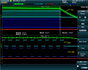
from the datasheet, SR1 should either complement to LSG or synchronized to LSG. Can you let me know at which condition will cause the SR to enter into abnormal status?

  • Hi,

    SR drive lost is likely due to reverse current protection. You can check SSSR capacitor voltage and RES voltage to determine. Please refer to the datasheet, Negative Current Protection, 7.3.12. If this is confirmed, then the fixes include increase the threshold of the protection on CS_SET, or increase your output inductor value. 

  • Hi Hong

    Thank you for your reply, we have confirmed the SSSR and RES voltage are all within the range before observing the abnormal behavior of SR. See below, before the SSSR(purple) and Vres(red) oscillation, the  SR1 lost for a long time(deep blue).

  • Hi,

    can you zoom in the area when SR started to lose its pulses from normal to pulse disappear? Also show SSSR RES CS SR1 SR2 and your aux bias voltage so to find what signals become abnormal when SR1 and SR2 from normal to not normal.

  • Hi Hong

    we are trying to capture the waveform when SR started to lose or became abnormal, this behavior didn't happen every time. it almost takes 4 hours to catch the abnormal once during an on/off test. from the datasheet, we didn't find information on which condition will cause the abnormal behavior of the SR. so which signal do you think will trigger the abnormal? SSSR or RES or CS?  and can we have a call with you ?

  • Hi,

    SSSR, RES, should be the reason. But if during the on/off, SS and UVLO may also be considered. You need to get the waveforms to see which signals become not normal so to cause SR pulse not normal. 

    If you look at SR reverse current protection you will see the datasheet describe when SR pulse becomes narrow. 

    if your finding at power off and on it may combine UVLO. 

    But you would need to find what become abnormal to help identify the reason. I am not sure how a phone call can help this.

  • Hi Hong

    we 've reviewed section 7.3.12 carefully, it's mentioned When the negative current limit is exceeded twice, the SSSR capacitor will be clamped to the ground so the controller enters the SR SYNC mode where the SR pulses are synchronized to the respective primary FET pulses.

    but you can see the waveform below(also longtime before the red cycled), the SR1 is neither synchronized nor complementary to the respective primary FET. Is there anything I missed in the datasheet? the phone call will definitely help us to clarify this issue clearly, please check. thank you

  • Hi,

    That section is to provide information when SR pulses becomes narrower to deal with the reverse current over the limit. The observation in your test could be from different reasons so you need to find when the SR started to become not normal then check possible related other signals. First you need to find when that issue can present so you can duplicate the issue when you need. Your message looks the issue presents in random way then it is difficult to make analysis. I see a meeting already set up. 

  • Hi,

    It looks we are in talk through email. So this thread can be closed. If you need to get support from E2E, you can reply or create a new thread.