This thread has been locked.

If you have a related question, please click the "Ask a related question" button in the top right corner. The newly created question will be automatically linked to this question.

BQ25672: Design

Part Number: BQ25672

Hi, I want to design a battery charge circuit for 2 lithium battery; however, the DS omits some calculation or information.

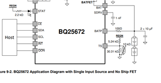
- TS --> DS states that is recommended to use 103AT-2 10Kohms as thermistor, but when I read the design procedure, I only see in the schematic a voltage divider


- ILIM_HIZ --> this pin is to set the current input limit of the circuit, right? And the formula is Vilim_hiz = 1V + 0.8*ILIM. How is a good current limit for a 2S charger configuration? How can I infer if a 500ma or 1.5A is a good current limitation. 

- Vsys --> how do I know the output voltage of the system? if I have 2S configuration, that mean Vsys would be 7V - 19V?

  • Hi Andres,

    Regarding 1, the TS pin resistors in the datasheet are for use with a 103AT-2 10kohm thermistor.  If you using a different thermistor, the equations on datasheet page 2 can help you size the resistor divider.

    Regarding 2, input current limit should be set to the max output current of your power source to the charger.  Otherwise, the charger might to try to pull too much current from the source and crash the source.

    Regarding 3, with 2S configuration, V(SYS) = MINSYS(default=7V) up to the slightly higher than the battery regulation voltage (default=8.4V).  The host can change the I2C register default values with a limited range.

    Regards,

    Jeff