This thread has been locked.

If you have a related question, please click the "Ask a related question" button in the top right corner. The newly created question will be automatically linked to this question.

LM2674: Overshoot at power-up

Part Number: LM2674

Hello,

We use the LM2674M-3.3 to supply micro-controllers in our products.
We recently had failures at power-up resulting in blowing IC connected to the 3.3V rail (IC in short circuit). 
The attached pdf contains the schematic of the stage used:

LM2674M-3.3.pdf

It seems there is an overshoot at power-up which energy is sufficient to destroy IC connected to the 3.3V rail.
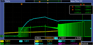
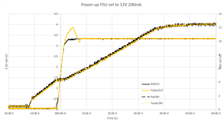
The below scope captures, compare the power-up on the same unit using an LM2674M-3.3 not causing an overshoot (black) and one causing an overshoot.
Note: 

- the secondary Y axis is the input voltage (12V limited to 200mA).

- the overshoot remains ~0.5V as limited by clamping diodes connected to an external 3.3V to protect IC.

Could you tell me what could be at the origin of such overshoot at power-up?

If after power-up, the 3.3V is shorted and then released there is no overshoot.

The inductor and the output capacitor values seem quite high compared to values from the datasheet. Could that be the cause of the overshoot at power-up?
The board is not a new design and has been manufactured without problem for more than 5 years.

Thanks for your help

Gilles

  • Hello Gilles,

    Sorry to hear about the issue.

    I want to say that you may be right in that the large inductance could be posing an issue. It seems like a lot of energy is being dumped out of the inductor after the soft start finishes. It is odd that the issue doesn't occur after a short circuit releases, as it is my understanding that coming of a short, the device has a similar startup sequence. To confirm, this failure is repeatable on the device? If so, it would be good to see some waveforms, with Vsw shown so we can better see the control behavior and if the low inductor current slew is posing an issue.

    I noted a few things in your schematic

    1. The inductor current rating seems low as it is annotated. I recommend having the saturation current of the inudctor greater than the max specified DC load current  (500mA)/

    2. Are the capacitors correctly rated for max input voltage?

    3. How is the 48V net (connected to SW through some components) used in this design? 

    It is odd that you mention that the design has been in production for quite some time without issue.

    Can you please share the failure rate?

  • Thanks for your answer.

    1) You are right, we should consider using an inductor with a higher current rating and possibly a lower value, however I have measured an inrush current of ~250mA in the inductor when the buck converter starts reducing quickly to less than 50mA, 

    2) Ceramic capacitors are rated 50V, input electrolytic capacitors are rated 35V.

    3) The set R1, C9, C10, D3 is a voltage doubler to drive high side N-MOS connected to the 28V rail. I have tried removing R10 to exclude this stage from the equation, but that did not change the amplitude of the overshoot.

    Concerning the failure rate, sorry, I don't have any valid information.

  • Hello Gilles, I believe it would be a worthwhile experiment to see if the issue is removed with a lower inductance. I would suggest using webench to calculate your inductor. I would expect something under 100uH

    Additionally, it would be good to see the additional waveforms so we can understand the device control behavior.

  • Thanks for your answer, I did not try with 100uH but with 330uH but did not notice any improvement regarding the overshoot (see below scope capture):

    CH1: input voltage, CH2: output voltage, CH4: switching node

    I have compared inductor and capacitor values returned by Webench to those currently used on our design and it seems the phase margin is probably too small on our design.  I am reluctant to use a smaller inductor and a smaller output capacitor as this product has been manufactured for year without problem and I only found one LM2674M-3.3 with an overshoot problem at power-up in a set of ~200.

  • Thanks, Gilles. Seems like you have a really slow moving vin. Sometimes that can pose issues and you might be bouncing in and out of boot uvlo (Vin very close to Vout). Have you tried startups with a faster slew? Also, can I assume this startup waveform was taken without load?

    If you have waveforms with a faster slew on Vin that would be good to see. Also, if you can provide a higher resolution image of this image, that will be beneficial. 

    I cannot see what the Vin voltage is as the "zero-marker" is off the screen, but based on the mean statistic measurement annotated on the scope, it looks like it is around 5.2V. Please correct me if I am wrong.