The TI E2E™ design support forums will undergo maintenance from July 11 to July 13. If you need design support during this time, open a new support request with our customer support center.

This thread has been locked.

If you have a related question, please click the "Ask a related question" button in the top right corner. The newly created question will be automatically linked to this question.

TPS23754: PoE ORing option for multiple power outputs

Part Number: TPS23754
Other Parts Discussed in Thread: PMP6812, TPS23731

Hi all,

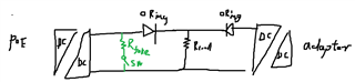
I would like to get advice about the most reasonable way to implement redundant power supply for my device by powering it via 2 DC power supplies and 1 PoE as backup.

My end-device needs 12V, 5V and 3.3V voltage outputs and will consume approx. from 3-25 Watts of power.

Both of the DC power supplies provide 12V output voltage. However, power will be consumed from one source - the power from the DC power supplies will be switched via a power MUX e. g. TPS2124Y.

For the PoE design I want to use the TPS23754 and use it with ORing option.

My concerns are:

1. Is it better for this case to use the ORing option 2 and design a flyback converter with 3 output voltages?

2. Or maybe using ORing option 3 and use another dc/dc converter for providing 12V, 5V and 3.3V to my device would be a bettter option?

I have already analysed some of TI's reference designs but anyway I want to make sure that the device will work properly and won't be oversized.

Any help is appreciated!

Best regards, Andrzej

  • Hi Andrzej,

    Thanks for reaching out.


    1. Is it better for this case to use the ORing option 2 and design a flyback converter with 3 output voltages?

    The PoE PD input voltage is 37 - 57 V. and your power supply is 12 V rated. If option 1 & 2 are used, the input voltage range will be 12 - 57 V.

    In flyback, Vout = Vin / N * D/ (1-D). The max duty ratio of TPS23754 is ~75%. Leave some margin and consider the max is 66%, which makes D/ (1-D) <= 2. 

    When you have max Vout = 12 V & min Vin = 12 V, you need the max D/ (1-D) = 2, which makes N = 2.

    When you have min Vout = 3.3 V & max Vin = 57 V, N = 2, you need min D = 10.4%. 

    I think you can design the flyback at option 2 but its wider operation range may make it a low efficiency one. And the secondary side diode / sync FET may need a high voltage rating.

    2. Or maybe using ORing option 3 and use another dc/dc converter for providing 12V, 5V and 3.3V to my device would be a better option?

    In terms of converter operation range, it is a better choice to separate the 37-57 V PoE voltage source and the 12 V power supply source. But you may need a larger BOMs cost to have two converters.


    Best regards,

    Diang

  • Hi Diang,

    Thank you for the provided clarification.

    I think, that in this case using ORing option 3 seems to be a better choice, since the converter can maintain its higher efficiency and won't require higher design complexity.

    With that being said, I have another questions:

    1. In this case, when the input voltage is 37-57V are there any other points to consider when picking the right transfomer (in terms of turns ratio, inductivity)?

    2. To meet the PoE power-up redundancy, is it possible to implement ORing option 3 as backup with hitless failover? According to SLV306A there is one possiblity but it dissipates power whole the time when PoE is present.

    Best regards,

    Andrzej

  • Hi Andrzej,

    Thanks for your reply.

    1. We have some reference designs with different output voltage levels with TPS23754. Besides, transformer manufacturers like Wurth, Linkcom, Pulse, Coilcraft, etc. all have PoE transformer (37 - 57 V input). You can search "the manufacturer name" + "PoE transformer" to view their products. 

    PMP6812 12 V 1.8 A PoE13F-12LB
    PMP6672 5 V 5 A JA4456-DL

    2. Yes, option 3 can make the hitless transition between PoE and adapter. 

    - Maintain power signature (MPS): if PD draw too low current for a certain of time, the PSE will turn off this PD's port. Some products like TPS23731 has the auto MPS can make PSE keeps on without additional circuit. But for TPS23754, you may need a fake load to keep the PD port still can draw >=10 mA when adapter is sourcing power and PoE is idle. 

    - The oring circuit needs to be carefully designed to make the either adapter or PoE have the priority. Sometimes it needs adjusting the feedback loop resistor divider to the error amplifier input to make one side has lower output voltage. 

    Best regards,

    Diang

  • Hi Diang,

    Thank you for the provided information. I think this solved my concerns with picking the right transformer. 

    To implement ORing option 3 with PoE as backup (adapter priority) I will try it with the TPS23754 since it has better availability at the moment compared to TPS23731. Nevertheless I will have to test this solution if it works properly for my design. If there will be a need, then I can share the results with you. 
    Thank you for your support!

    Best regards, Andrzej