This thread has been locked.

If you have a related question, please click the "Ask a related question" button in the top right corner. The newly created question will be automatically linked to this question.

BQ78Z100: Turn on the charging and discharging Mosfets using BQ78Z100DRZT

Part Number: BQ78Z100
Other Parts Discussed in Thread: EV2400, BQSTUDIO,

Hello TI Team,

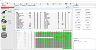
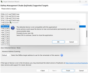
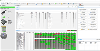
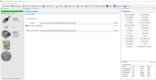
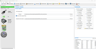
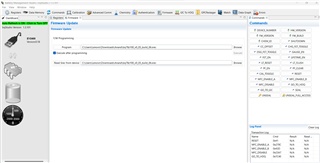
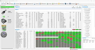
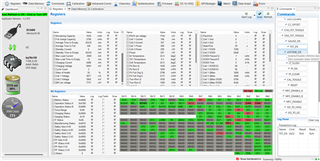
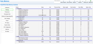
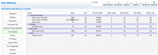
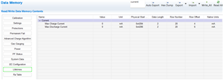
I am struggling to turn on the charging and discharging Mosfets BQ78Z100DRZT,
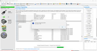
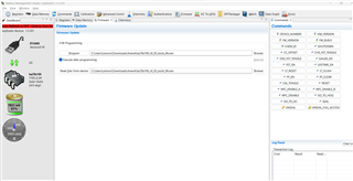
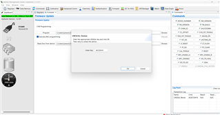
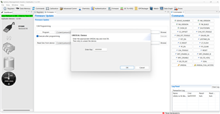
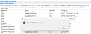
Configure and upload the firmware using the EV2400 Evaluation module.

I have used external Mosfets for balancing the cells.

Battery Details
2000mAh,
2Cell in series,
4.2V DC per cell.

Please find the attached schematic.

BRs
Murthy

  • There is no schematic attached.

    The CHG and DSG FETs that the gauge can control are for protection, not for cell balancing.

  • Please find the attachment,


    Hello

    Dominik Hartl11

    ,
    I am not talking about this external Mosfets CHG and DSG FETs. I have used two more external Mosfets for cell balancing.

    Chagring Mosfet is working from BQStudtio Charging Toggle button.
    I want this IC should work Standalone, After detecting the load, it should start discharging impetuously and After connecting charger, it should start charging automatically.

    Guide me to configure BQ78Z100DRZT.

    BRs
    Murthy

  • The gauge will turn off the DSG and CHG FETs based on protection events. Please check that none of the events are triggered. You can read the status in bqStudio (SafetyAlert and SafetyStatus etc.) in the register view.

  • Hello Team,

    I am not able to program battery chemistry, It is generating error code = 1703, and the message: firmware version in bcfqx does not match firmware version of the connected device.

    I have updated the firmware to the latest version (bq78z100_v0_05_build_06.srec) on the Texas Instrument website.

    I am finding it difficult to make the bq78z100 operational.

    Please find the screenshots register.


    I completed the calibration of the gauge.
    I can turn on the Charging FET from the commands FET_EN & CHG_FET_TOGGLE.


    I am not able to enable the gauge permanently. Guide me on how to enable this.

    BRs
    Murthy

  • Please make sure that you restart bqStudio after programming a new FW version. bqStudio also must auto-detect the correct version. Your screenshots show 1100_0_04, which isn't a match for bq78z100_v0_05.

    Also please make sure that this file is in the bqStudio config folder: https://e2e.ti.com/cfs-file/__key/communityserver-discussions-components-files/196/1100_5F00_0_5F00_05_2D00_bq78z100.bqz

  • Hello Team,

    I restarted the bqStudio after programming a new FW version.
    bqStudio is not detected as the correct version.Please find the screenshot


    I have copied this file 1100_0_05-bq78z100.bqz to the bqStudio config folder.


    I tried to enable the GAUGE_EN Command. Later on, I tried all other commands, But it shows the message N/A as shown in the screenshots.

    I mistakenly press the UNSEAL and UNSEAL_FULL_ACCES.
    Now my device got sealed. Please let me know how to unseal it.

    Please let me know, How many steps are required to enable the gauge.

    BRs
    Murthy

  • If auto detect shows "None" then bqStudio didn't even find a device. bqStudio queries the EV2400 via USB HID for devices on its I2C or SMBUS or HDQ connector. If it says "None", then bqStudio either wasn't able to talk to the EV2400 or nothing responded on the I2C or SMBUS or HDQ.

    You first have to make sure that bqStudio auto detects something other than "None". I highly advise against selecting a specific gauge and ignoring the warning.

    Please disconnect and reconnect the EV2400 and make 100% sure that the gauge is powered up and connected to the correct interface port on the EV2400.

    If bqStudio keeps auto detecting "None", you can select the gauge manually (without the objective to use it for gauging but with the objective to find out why bqStudio auto detects "None") and then try to read one byte from I2C address 0xAA, register 0x00 in Advanced Communications. bqStudio will show additional error information on the bottom status bar. It will either report that it can't find a communications adapter (then the problem is with the EV2400 or your Windows USB HID driver) or it'll report that the gauge didn't acknowledge the command (then the problem is with the connection between the EV2400 and the gauge or the gauge isn't powered up or something else is broken on the bus - this would often require further debug with a dscope and probing the bus (SCL/SDA) or the power supply for the gauge).

  • Hello Sir,

    I have connected the device through I2C, Now it is connected with bqStudio.

    I am a Hardware design guy, I am newbie to software.
    I cannot ablet to type this 0xAA, register 0x00 in Advanced Communications.

    Programmed the chemistry successfully

    I am not able to enable the BQ78Z100DRZT using the GAUGE_EN command.

    BRs
    Murthy

  • So did bqStudio auto-detect the gauge (=you didn't have to select the gauge from the list)? If so, then this step was successful.

    GAUGE_EN will enable the impedance tracking algorithm. It will not enable the CHG and DSG FETs. Your screenshot shows that both the DSG and CHG FET are disabled. (XCHG and XDSG are red/1). Please issue command FET_EN (and verify this by checking ManufacturingStatus, Bit 4. This must be red/1).

  • Hello Sir,

    Yes, Bq Studio is Auto detecting now.

    I have observed after pressing the FET_EN command, Noticed Manufacturing Status, Bit 4 become RED. Please check in the sceenshot.after current flowing more than approx 1.15 A for some duration.
    Bat Voltage: 7.858
    Charger Voltage: 8.1VDC

    Observer XDSG appeared continuously Green on Bqstudio GUI.

    After that, I tried to repeat the FET_EN command, But I have not noticed any current drawing from the charger.

    I have changed some parameters in Data memory, as the screenshot below, and tried again after pressing FET_EN.

    BRs
    Murthy

  • Bit 4 in Manufacturing Status = 1 (red) is ok and indicates that the gauge controls the FETs.

    XCHG is 1 because OCC got triggered (see OCC in SafetyStatus()). The protector detected and over current in charge fault. So it looks like you applied a current that is too high and as a result the protector in the gauge disabled the charge FET.

  • Hello Sir,

    Please let me how to remove this OCC error?.

    I want to enable the gauge for charging and discharging?, which parameters do I need to change?

    BRs
    Murthy

  • You can raise the threshold for OCC. See TRM https://www.ti.com/lit/ug/sluub63a/sluub63a.pdf, 2.4

  • Hello Sir,

    I have set OCC threshold parameters already, but still have not Noticed the charging FET ON.
    I did power ON/OFF the device once and after pressing the Reset Command, Then I tried to turn on the charging Mosfet, and now it's working normally.

    Please answer all of the below 4 queries.
    1. I have tried to press the GUAGE_EN, But it is not turning On the CHG & DSG FETs.
    2. How to enable the charging and discharging algorithm?
    3. I want to enable the gauge autonomously, without BQ Studio being connected. Now it is working by only passing the commands through GUI.
    4. How I can find out if balancing is happening with external cell balancing MOSFETS?

    I have tried few parameter setting as below.

    BRs
    Murthy

  • #1: GAUGE_EN controls the gauging algorithm, not the protector (which is not part of the gauging algorithm but a separate function inside the bq78z100 chip). FET_EN controls the protector. You only have to issue FET_EN once. The gauge will set a flag in Manufacturing Status (which is stored in flash memory) and it will keep the protector enabled from this point on.

    #2: The gauging algorithm, which has three distinct states (charging, discharging, relax), is enabled with GAUGE_EN.

    #3: You can issue GAUGE_EN and FET_EN from your host uC (see TRM for command info https://www.ti.com/lit/ug/sluub63a/sluub63a.pdf). See #1. Once these features are enabled, they stay enabled. So if you would enable them (e.g. in the golden image that you program to the gauge during production), then you don't have to enable them again.

    #4: The gauge can control internal bypass FETs to balance cells to a certain extent. Details are in chapter 7, TRM.

  • Hello Sir,

    Appreciate the quick response to all my queries.

    From where I can tap the power from Battery +ve or Pack/Charger +ve or for Host Microcontroller?
    I think to tap it from the battery directly. Please share your Insights.

    How much data it can store internally inside the Gauge If I wish to log the Data?

    BRs
    Murthy

  • The system should be supplied via PACK/CHARGER.

    You can use 32 bytes in class System Data. See bqStudio, Data Memory, System Data.


  • Hello Sir,

    First Query:
    If I connect my host Microcontroller PACK/CHARGER,
    In case of an OCC fault or temperature fault, Microcontroller will lose the power right?
    Then gauge will not be able to enable the charging and discharging of FETs, Without the FET Enable and Gauge Enable Commands?

    That time I need give reset to the gauge from Host Microcontroller after connecting the charger, Then I need to send FET Enable and Gauge Enable commands?.

    Second Query:

    I have noticed battery charging, I made the cutoff volatge is 4.25V,
    But the gauge allowed the chager to charge more than 4.25V?
    Pelase let me know how to resolve this?

    Simmilar with respect to current?

    Gauge will enable the contant current charging, What ever voltage applied on gauge Pack teriminal ?
    What will be the recommended voltage of Charger, I am planning to use 9V Charger, is it good enough for 8.4V full charge battery?

    I noticed after the battery was Fully charged, Zero Current from the charger, Then I tested the Voltages at Battery Teriminal: 8.51 VDC and at Charger Teriminal: 8.11 VDC.
    I am expecting 8.51VDC for the load, Maybe one MOSFET is ON and Another MOSFET is off.

    BRs
    Murthy

  • The CHG FET has a body diode so if it is off, there's still a voltage on PACK/CHARGER. Once your system draws current, then the gauge will turn on the CHG FET to protect this body diode and it will turn it off again once the current drops below the quit current threshold.

    You only have to issue the FET enable and Gauge enable commands once. The effect is persistent (the gauge writes this to flash memory). You don't need to do this all the time.

    The gauge doesn't control the charger directly so if your charger keeps charging above 4.25V you'll have to check why your charger doesn't stop.

    The gauge will protect the battery from excessive conditions (current, temperature) but it will not control the charger. It can inform the host what charging voltage and current is recommended (that's what the charging settings are for) but the actual charger control is with the host and charger, not the gauge.

    This gauge has a lot of registers that can be configured. This should be done with bqStudio during development and once it works well, export the flash image, which can then be programmed in production or with a uC. The file format is Flash Stream. See Flash Stream File Format 1. IntroductionTexas Instrumentshttps://e2e.ti.com › cfs-file › __key › 5164.Flas...

    After the gauge is programmed with the image, all you have to do in your host uC is read result (e.g. read SOC or Voltage).