Other Parts Discussed in Thread: TPS7A4701-EP,
Hi,
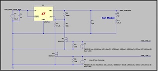
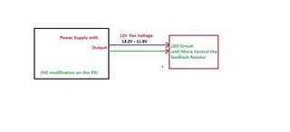
Our application is to use this LDO part TPS7A4701-EP in adjustable opration with switching some values on the R2.
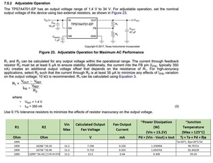
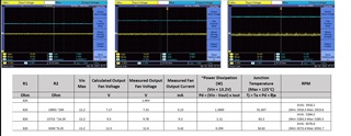
Could you help check if R2 Values and Calculated Vout doesn't violate any specs on this TPS7A4701EVM-094 device like Volatge dropout, etc?
I had evaluted this using the TPS7A4701EVM-094 and here are my questions:
Questions:
1. If I lower the 47uF Cout to 10uF are there any issues (tested in ambient temp seems not much difference in Vout signal),
Might this be a concern at low and max operating temp?
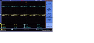
2. Is there a chance to minimize the ripple at 12.5 Output voltage? I tried to add decoupling (1uF, 0.1uF on input voltage)
Thank you in advance.
Kind Regards,
Rosalino