This thread has been locked.

If you have a related question, please click the "Ask a related question" button in the top right corner. The newly created question will be automatically linked to this question.

LM74502: Problems switching on when the load is low resistance.

Part Number: LM74502

I have an array of 5 MOSFETs being controlled each by a single Lm74502 with a 3.3v enable signal.

For 4 of these everything works great, however one of my loads is a 6 ohm resistive heater that would not switch on when the heater was connected. With no load it switched fine and with a 7kOhm DC brushed fan it switched fine.

If I connected the heater and the fan in parallel, the mosfet switched on and off fine as well. Also if I switched the mosfet on with no load connected and then connected the heater afterwords the mosfet would stay on and switched off just fine but would not switch back on.


Any help in understanding what is happening would be great, or steps I can take to gather more data to make the problem more apparent.


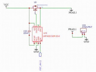
Below is the mosfet I am driving with the LM74502 as well as the schematic

https://www.digikey.com/en/products/detail/infineon-technologies/IPB030N08N3GATMA1/2080892


  • Hi Jarett,

    Welcome to e2e!

    Firstly, I would recommend you to connect the OV pin to GND. 

    Next, Please share waveform captures during failed startup with VS, VCAP, SRC and EN signals captured. 

  • Here are the captures, let me know if there is any settings I need to change I almost never scope anything and I never have to provide any scope output in a standardized format others would be familiar with / easily readable.
    I included gate as well.


    EN1, EN2


    VS1, VS2

    VCAP1, VCAP2, VCAP3

    Gate1, Gate2

    SRC1, SRC2

  • Hi Jarett,

    Thanks for sharing the waveforms

    1. Have you connected the OV pin to GND? If not, connect it to GND.
    2. From the waveform captures, it is visible that the VS pin has voltage spikes occasionally.  You will have to add some input capacitance to make it stable.
      1. Add a minimum of 0.1uF each at the input and at the output. If required, you will have to increase the Cin to make VS pin stable.
    3. Once you make the VS pin stable, the GATE would also become stable and will remain ON. 
  • Yes OV is grounded

    Adding capacitance from SRC/Output to ground fixed the problem.

    As I wanted to have a better understanding I tested VC to ground and SRC to ground separately and only SRC to ground helped. Which explains why a separate load in parallel also worked since the wire had some capacitance.
    I will say adding capacitance on VC to ground did allow for a wider range of suitable capacitor sizes to work on SRC to ground.


    If possible I would like to better understand why adding capacitance on src to ground fixed this. I understand if you can't explain for whatever reason.

    I also don't understand why VS is spiking at each turn on attempt. Obviously VCap jumps because VS jumps but I would expect VS to drop blow steady state before coming back up to the lower voltage caused by the load.