This thread has been locked.

If you have a related question, please click the "Ask a related question" button in the top right corner. The newly created question will be automatically linked to this question.

BQ76952: Problems on specs of BQ76952

Part Number: BQ76952

Hi team,

my customer is using BQ76952 and they are having new problems as below:

1. My customer wants to use BQ76952 as low side drive and there will be some pins left unused such as PCHG and DCHG. Then how will my customer deal with the unused pins? Do we have a guide on how to use BQ76952 on low side drive?

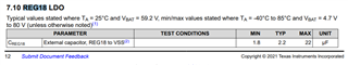
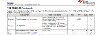
2.If BREG isn't connected, will there be output on REG1&REG2? And can BREG be unconnected?

3. When in sleep mode, will there be extra power consumption on pins of SCL and SDL?

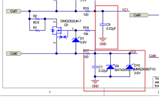
4.Do we need to add extra diodes on VC0 and VC1 to prevent negative voltage?

5. There are some capacitors on pins such as REG18 and REG1. Can i change the capacitance or just follow the capacitance on EVM user guide?

  • Hello Zoey,

    1- There is a low side reference design TIDA-010216

    There's also an app note for design considerations and circuit concepts for low side driver. "Using Low-Side FETs with the BQ769x2 Battery Monitor Family"

    Unused pins are discussed in Table 16-3 Terminating Unused Pins in the datasheet.

    2- If this pin is not used and pin 36 (REGIN) is also not used, both pins should be connected to pin 17 (VSS). If this pin is not used but pin 36 is used (such as driven from an external source), then this pin should be connected to pin 36 (REGIN). 

    The REG1 and REG2 are fed from REGIN pin. REGIN pin can be powered by an external source. All the REGIN pin needs is 6V to feed the regulators.

    3- The device still communicates in SLEEP mode, not as often as NORMAL mode. Typical current consumption in Sleep mode is about 41 uA.

    4- The TIDA-010208 reference design uses a Zener and a Schottky diode in VC0. The Zener protects the pin from high voltages that could exceed abs max. The Schottky diode protects the pin from too low of voltages. Notice how we also reference the VC1 and VC0 filter caps to GND. This is to ensure BAT- does not go below VSS.


    5- The user guide probably has the recommended value. I suggest to follow the Abs max on datasheet for the capacitor values if the user guide values will not be used.

    Regards,
    Jose Couso

  • Hi Jose,

    Many many thanks for your patient explanation!! it is really help!!

    For the 5th point, where can i find the abs max of the capacitor values?

  • Hello Zoey,

    It can be found in the datasheet. Please see below.


    Regards,
    Jose Couso