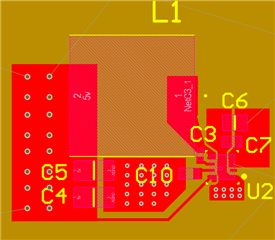
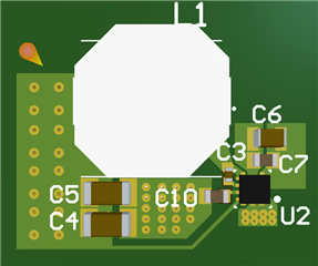
Hi, Please could you check that my scheamtic and PCB layout for this component for a 5v fixed outout.
Schematic - 
PCB 2D view - 
PCB 3D - 
Thank you!
This thread has been locked.
If you have a related question, please click the "Ask a related question" button in the top right corner. The newly created question will be automatically linked to this question.
Hi, Please could you check that my scheamtic and PCB layout for this component for a 5v fixed outout.
Schematic - 
PCB 2D view - 
PCB 3D - 
Thank you!
Hello, the schematic looks acceptable.
In regards to the layout, I would see if they can pour ground in the top layer (assembly layer). This would be especially beneficial with small size, or low layer count boards.
Hello, is there any improvement that can be implemented on the schematic side?
As for the layout, this is a 200x180mm 4 layer board. Do you mean just flood the whole top layer with a ground pour to fill all gaps? Thank you!
Schematic looks good.
As for the layout, this is a 200x180mm 4 layer board. Do you mean just flood the whole top layer with a ground pour to fill all gaps?
Yes, more ground the better in the top layer.