This thread has been locked.

If you have a related question, please click the "Ask a related question" button in the top right corner. The newly created question will be automatically linked to this question.

UCC28180: UCC28180D

Part Number: UCC28180
Other Parts Discussed in Thread: PMP20612

Hello Experts, 

I am using UCC28180D for 1 KW PFC+LLC charger application. 

Facing issue with PFC failure when AC mains turn ON . MosFET become short circuit between All terminals (S, D, G) and IC UCC 28180D also failing.

Below are PFC section components:        Switching frequency:  70KHz. 

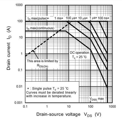
1) MosFET used Toshiba - TK25N60X5 , 

2)Boost inductor- 1m H ,15A.

3) PFC output capacitor: 560 u F/450V,

4) Rsense : 10 m Ohm.

5) CISENSE: 1.5 n F, RISENSE: 220 Ohms 

6) CICOMP: 2.2n F 

7) RVcomp :   7.5Kohm,  CVcomp : 10 u F, CV comp_p  : 1 uF

looking for quick feedback and if any suggestions. 

please find attached filled calculation sheet  

thank you .


sluc506c_ Calculation PFC.xls

  • Hi Vikas,

    Thank you for the query on UCC28180.

    IThe sense resistor choice assumes a universal input voltage range of 85V to 265V. If the input range is only 165V to 260V the current sensing resistor does not change from the value calculated for the 85V low line value and it is incorrect to double the value of CS resistor on the basis that the currents at 187V are (approx) half those at 85V. The value of 10mohms looks ok but just wanted to mention this.

    The second point I would make is that it may be necessary to add a diode from ISENSE to GND if there is any possibility that the voltage on the ISENSE pin could exceed -1.1V. this can happen during the inrush current phase when the PFC stage is first connected to the line. If this voltage exceeds -1.1V at inrush events, the internal circuitry may work abnormally due to the internal circuit parasitics.

    Third, Rvcomp should be close to 13.3kohm and Cv_comp around 0.68uF and ensure the startup diode for inrush current llimit is present.

    The above are suggestions based on your calculations and once you have verified above please proceed with the below steps.

    To check for MOSFET failure, can you please confirm if the failure is after turning the AC voltage ON or after turning on the controller? Can you check the voltage on Gate to see if there is any ringing above the ABSMAX rating of the pin? Similar check needs to be done on the drain pin also to check if excessive drain or souce side inductance ringing is above ABSMAX rating of the device. I would suggest to start from low load/ voltage to see where the failure is starting to occur.

    Regards,

    Harish

  • Dear Harish ,

    Thank you for your quick feedback. 

    We have used Diode (BAS21GWX) at Isensee to GND . 

    Startup diode is used . 

    what is impact of capacitor at ICOMP pin ? 

    If we used 100n F instead of 2.2 n F , will this cause the failure during start up?

    Thank you  ,

    Vikas 

  • Hi Vikas,

    Thank you for the reply. The diode looks (BAS21GWX) looks fine to me. BAV23c from Vishay is also used widely.

    100nF will kill the phase margin and your current loop will be unstable. So it is better to use recommended values to avoid uncertainities in performance.

    Regards,

    Harish

  • Hello Harish,

    Thank you for your reply , 

    I have corrected the value of capacitor but still getting the issue of MOSFET failure during AC mains turn ON . 

    i have investigated the Vds of Mosfet not exceeding 450 V while i am using 600V mosfet  . Gate voltage also not exceeding Max Vgs rating of Mosfet .

    I am using current sense 10 mohms  , Do you feel any issue with current sense value ?

    I have increase the Current sense resistor to 15 ohms, but failure remains. we saw peak current of 60A for 30 msec when Mosfet failed. Ans Voltage at

    Isense  pin was - 0.75V  . 

    We have suspect that Most of time failure happening when PFC not discharged or VCC > 9.5V available to PFC controller ( when PFC controller active)  .

     please provide your feedback on this . 

    Thank you  , 

    Vikas 

    please share your email address for further communication. 

  • Hi Vikas,

    Thank you for the reply.

    I think your component values look fine to me. Sorry that changing the current loop capacitance did not help much. The current sense resitor is ok at 10mohms. The higher value of 15mohms is not a corrct approach.

    I would suggest increasing the value of RISENSE which is currently 220 ohm in the current schematic, the high inrush current is probably, so can try increasing this to 3x times the current value and see if this helps.

    Second thing is that I feel during this period it affects the Safe operating area of the device. This could probably be the reason for blowing of FETs at startup

    Can you try to check at other lower loads than 1KW and see if there is any difference? Also if possible try using a higher current rated FET temporarily to see if this is what is causing the failure.

    Third possibility could be that, normally a controller that measures input voltage will go into brownout when the high voltage input drops below a set level.
    In brownout, the soft start capacitor is discharged and once the input voltage is re-applied the soft start cap starts to charge again.
    This causes a gradual increase in gate drive pulse width. But with the UCC28180 if the high voltage input drops out the gate drive goes to max duty cycle because the input voltage is not being monitored and all the UCC28180 see is that VOUT is low.
    Once the input voltage comes back online (meaning when you turn on), the converter will go to an over voltage condition because of the slow loop response of the pfc.This is causing damage to MOSFET. We need to see point no. 2 & 3 separately but effects could be pointed to the current withstand capability of MOSFET.

    Please let us know your observations.

    Regards,

    Harish

  • Hello Harish , 

    I reach to same opinion as you.  I recognize that UCC28180 not sensing the drop in input voltage when Ac mains switch off.  So it is not implementing soft start when AC mains reapplied again before IC VCc is not going in UVLO  fault . I think this make Mosfet to turn on abruptly and takes huge Inrush . 

    Please let me know your thoughts on this . 

    Regards 

    Vikas

  • Hi Vikas,

    In addition to what I suggested in my previous post, we can try a couple of things together you an try too to address this situation.

    1. Tune the soft start time.  Besides capacitor (Cvcomp_p)on VCOMP pin, there is other Resistor + Capacitor (Rvcomp+Cvcomp) on VCOMP pin. Cvcomp_p affect soft start time, Rvcomp+Cvcomp mainly affect the loop response. So changing Cvcomp_p affect soft start time a lot, but affect loop response a little. 

    2. Add Brownout detection to detect to detect the drop in AC input voltage. 

    The circuit basically  pulls VSENSE below the OLP voltage level when VINAC is below the brownout point.

    brownout.pdf

    You can also check PMP20612 also for the implementation.

    https://www.ti.com/cn/lit/df/tidrqy2/tidrqy2.pdf?ts=1663301200007

    Thank you

    Regards,

    Harish