This thread has been locked.

If you have a related question, please click the "Ask a related question" button in the top right corner. The newly created question will be automatically linked to this question.

UCC28634: Secondary controll

Part Number: UCC28634
Other Parts Discussed in Thread: UCC28610, UCC28740, LM5023, UCC28600

Hi,

We already use a circuit with primary side controll for USB power. Now we wish to upgrade to proper high power USB Power Delivery protocols but the PD ICs require that the flyback converter is controlled by secondary feedback. Here is a typical application of the USB PD IC which needs secondary feedback. (https://datasheet.lcsc.com/lcsc/2202252030_Shenzhen-Fuman-Elec-IPT2601_C190620.pdf)

Is it possible to use the UCC28634 with secondary opto feedback?

Thank you and best regards,

Samo Smodiš

  • Hi,

    Thank you for the query on UCC28634.

    The UCC2863x is a PSR controller, so you will need to use one of our SSR controllers if you'd like to use an optocopuler based feedback.

    I recommend looking at UCC28600 first, then LM5023 and UCC28740 third.  UCC28610 would be a good fit as well.

    Regards,

    Harish

  • Hi Harish,

    Thank you for the quick response.

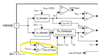
    I understand that the UCC28634 is a PSR controller however looking at its internal structure I dont understand why it would not function as a SSR as well. I mean, it samples the output voltage once during the switching period and it could get this information from the bias winding (PSR way) or from opto feedback (SSR way). The only problem I see is that it also samples Vin information during gate on-time. How would the IC react if it samples 7.5V, which is the output voltage feedback reference, as the Vin sample? I see that it could triggled Line UV fault but I cannot find the voltage reference Vac(min) at which it triggers.

  • Hi Samo,

    The minimum AC input voltage is 80V for startup below which it will be considered as input UV fault. This is mentioned in page-52 of datasheet.

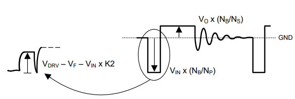
    So the voltage during ON time is going to be Vdrv-Vf-Vin*K2

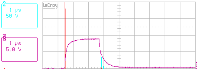
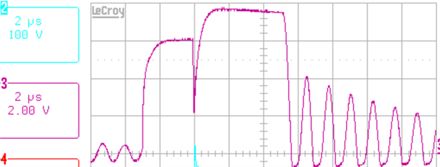
    70V ac rms input (8.5-9V at VSENSE - controller off)                                                                                                           140Vac rms input (6V at VSENSE)

    So you might want to check by increasing the input voltage close to 80V and see corresponding voltage on VSENSE. 

    Regards,

    Harish

  • Thank you for the explanation Harish.

    We will take you advice into consideration. Thank you also for SSR ICs.

  • Hi Samo,

    Thank you for the reply. 

    Regards,

    Harish