This thread has been locked.

If you have a related question, please click the "Ask a related question" button in the top right corner. The newly created question will be automatically linked to this question.

TPS25750: TPS25750

Part Number: TPS25750

HI

I am using TPS25750D without any issues, and I have a question about the default PDO settings.

After creating a Low Region Binary file from the Standard Configuration in "TPS25750_Application_Customization_Tool" and inputting it into the PD,

I connected a 12V PD charger and it outputted 12V without configuring the PDO settings.

I am curious about how the PDO default settings are configured.

Could you please provide information on this matter?

  • Hi Swengwoo, 

    The configuration should be the full flash image not just the low region binary. If you load the low region image without any configuration, the device will behave in the default configuration based off the ADCINx decoded values.

    Regards,

    Brandon

  • HI

    We outputted a Low Region Binary file without using EEPROM.

    Both ADCIN1 and ADCIN2 are connected to 1.5V. In this case, what is the default configuration?

  • Hi Swengwoo,

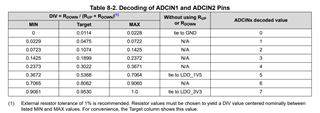
    Here based off the chart, your ADCINx decoded values correlate to 5,5.

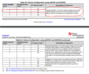
    Using this, you can see the default configuration of your device below:

    Therefore, the device will always enable the sink path until a configuration is loaded. 

    The low region will not contain any of the configuration that you need, you will need to generate full flash binary in order to encompass your configuration.

    Regards,

    Brandon

  • Hi Brandon,

    Could you let me know in which document contains the Decoding ADCIN pins table (Table 8-2) you attached.

    Regards

    Aman Bahl

  • Hi Aman, 

    The data sheet currently is lacking the decoded value table and we are fixing internally. We will release as soon as we have made the fix.

    In the maintime, you can reference the decoded table above!

    Regards,

    Brandon

  • HI

    I don't understand.

    Even though it was mentioned that the necessary configuration is not included in the low region,

    when the .c file is downloaded and executed from the low region, it successfully retrieves 12V from the 12V PD.

    Please explain why this is happening.

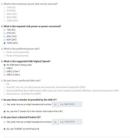
    I have set it up as follows.

  • Hi Swengwoo,

    I apologize I made a mistake, the low region does contain a configuration. It does not contain the header region. Therefore, the full flash image will contain basically a 'duplicate' of the low region along with the header.

    Regards,

    Brandon

  • GI

    If you configure the TPS25750 according to the Standard Configuration shown in the diagram and generate a Low Region Binary file for downloading, will it be configured to provide the highest voltage when connected to a 5V, 9V, 12V, 15V, 20V / 5A PD 3.0 100W charger?

  • Hi Swengwoo,

    If you configure according to the standard config shown in your diagram, you will still need full flash image as this contains the header information needed for CRC check. 

    The full flash image will be able to negotiate high voltage contracts up to 100W. 

    Currently in this version of the GUI, there are some errors in interfacing with BQ device that is on TPS25750EVM. We are aware of this issue and this will be fixed in the latest version of the GUI. This will only affect sourcing above 5V.

    Regards,

    Brandon

  • HI

    I understand that the full flash image contains the necessary header information for CRC checks, indicating that it is capable of negotiating 100W high voltage contracts. However, it is unknown how the Low Region File will function in such negotiations.

    does this mean?

  • Hi Swengwoo,

    The low region contains the patches along with your configuration. This image is duplicated in the full flash and also contains header information for the CRC check. You configuration will be loaded from the low region so therefore you can negotiate 100W contracts.

    Regards,

    Brandon