This thread has been locked.

If you have a related question, please click the "Ask a related question" button in the top right corner. The newly created question will be automatically linked to this question.

BQ40Z80EVM-020: Capacity not updating to the Data Memory Value

Part Number: BQ40Z80EVM-020
Other Parts Discussed in Thread: BQ40Z80, GPCCHEM

Hello,

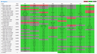
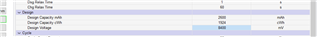
I am working on a 2-cell design with the BQ40Z80. I have set the cell count to 2 and also written the mAh, cWh, and pack voltage values to Data Memory. See below:

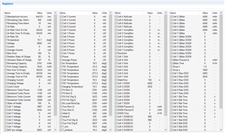
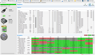
However, after resetting the device, it still reads as zero capacity and the Remaining Capacity Alarm is preventing the charging path from turning on. Cells are each at 3.9V, so nowhere near empty and the analog front end appears to be reading them correctly. Remaining cell inputs are shorted together on the EVM terminal block. See below:

I have a couple questions about this.

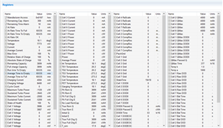
1) First question is obviously why is does the EVM read as 0mAh for both remaining capacity and (especially weird) design capacity?

2) Absolute SoC is 0%, but Relative SoC is 100%. What does that mean? Relative to what?

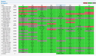
3) Run time to empty, Avg time to empty, and Avg time to full are all maxed out 0xFFFF. What does that mean?

Is there a better quick start guide than the EVM instructions? They don't help at all really, and the TRM is very dense. I'm working my way through it, but I would like to get some basic experiments off the ground in the meantime just to verify a design.

Thank you,

Jamie

  • Hello Jamie,

    The first steps for getting accurate results is to upload the chem ID, you can find the best match using the GPCCHEM tool. Then you need to complete a learning cycle. After this point you should get better results from the gauge.

    The FAQ page has the application notes for learning cycle. Here is the GPCCHEM tool: https://www.ti.com/tool/GPCCHEM

    Sincerely,

    Wyatt Keller

  • Hi Wyatt,

    I have tried programming a chemistry in and still get this result. I would say that this is not really about accuracy since the batteries are not off by a couple percent, but rather the gauge thinks there is 0mAh capacity remaining with a terminal voltage of 3.9V. Something else seems to be wrong. Also, since I can't get the outputs to turn on (either charge or discharge FETs), I won't be able to run a learning cycle. Anything else I can check first?

    Thanks,

    Jamie

  • For reference, I have attached the .gg file export for the current settings.3733.test.gg.csv

  • Hello Jamie,

    Usually when capacity is reported as 0 there are incorrect settings programmed. Have you programmed the correct terminate voltage and the number of cells for your system?

    Sincerely,

    Wyatt Keller

  • Hi Wyatt,

    I made some progress last night. It turns out the IATA settings for RM and FCC (both mAh and cWh settings) were all set to zero by default. When I set these properly, I was able to clear all errors and manually control the output FETs. They were reading incorrectly, but after a brief charge cycle, the capacities are close to correct. To be clear, they are still off from nominal, but at this point I've made no attempt to calibrate or learn, so that is to be expected.

    My next challenge is that the output FETs are not turning on automatically. I can command them on and off, but in the final application, we can not use SMB to command the pack on, as the pack is what supplies the power to the micro that would issue the command. I have pulled the SysPres pin low, and also tried setting the non-removable bit, but the FETs still stay off until I command them on. Can you help with that. 

    Latest settings are attached.

    Thanks, JamieJMtest_EVM_2Cells_4-27-23.gg.csv

  • Hello Jamie,

    When the FET_EN bit is set to 0 you will have manual control, when you want the firmware to control the FETs you should set FET_EN to 1. If they are still off then it means one of the conditions as defined in the TRM is not being met:

    If this does not help send a short log so we can see all the registers when the FETs are not turning on, or screenshots of all the registers on the register page.

    Sincerely,

    Wyatt Keller

  • Awesome, thank you. I will try this over the weekend and let you know.

    -Jamie

  • Hi Wyatt,

    I have been making some progress. The EVM kit is working now, so we switched to our prototype board with the same settings (i.e. export from the EVM, import and write to the prototype). However this is not working. Specifically, the FET gate voltages are off. I did a compare on the registers from the EVM and prototype and the summary of the differences, with my questions, is shown below:

    For a complete view, in case I missed anything, here is the registers and live readings for the working Eval kit:

    Here is the same screen shots for the prototype board:

    Thank you.

    -Jamie

  • Hello Jamie,

    If the FUSE bit is set you will not be able to turn on the FETs, which is why they are disabled. You will need to clear the FUSE bit first. Generally this is set when the secondary protector blows the fuse and the gauge senses the voltage on the FUSE pin. Can you share the schematic? If you do not use the FUSE pin make sure it is grounded and disabled in firmware so it doesn't float and trigger the fuse randomly.

    Sincerely,

    Wyatt Keller

  • Hi Wyatt,

    The Fuse pin was left floating in our design. I can probably run a rework wire to test if this fixes it. I have attached the schematic for review. How do I disable the fuse pin in FW? Thank.

    -Jamie8741.BMS.pdf

  • Hello Jamie,

    You cannot disable the fuse input with FW, the FETs will be turned off if the voltage on the FUSE pin is higher than the input high threshold, it is a hardware protection. If you do not use the FUSE you should disable it in FW, so that if the protections indicate a FUSE should be blown (permanent failures) the gauge won't try to drive the pin when grounded. Using a blue wire fix should resolve for your testing.

    Sincerely,

    Wyatt Keller

  • Hi Wyatt,

    I'm not sure I understand. In the first sentence you say "You cannot disable the fuse input with FW" but then later you say "If you do not use the FUSE you should disable it in FW". Can I disable it or not? If I can, how do I do that - i.e what settings should I be using? I will put the rework wire in place and try it though. Also, according to the datasheet, Fuse pin is only an output. Is it being monitored internally, and therefore more of a bidirectional pin?

    -Jamie

  • Hello Jamie,

    The FUSE pin is an input and output, if the voltage input is above VI(H) the FUSE bit will set and FETs will disable. This is all done in hardware and there is no firmware that can stop this behavior. The FW can use the FUSE pin as an output to blow the fuse, this is what I mentioned you should disable since you are not using a fuse in your system. If the fuse is enabled and the fuse pin is grounded it will cause damage if the gauge tries to drive the pin high.

    Sincerely,

    Wyatt Keller

  • Hi Wyatt. I just wanted to get back to you to close the loop. Grounding the Fuse pin was the solution. Charge and Discharge FETs are both turning on and all seems to be working. Thank you for all the support.

    -Jamie