


Other Parts Discussed in Thread: BQ40Z50
Hi
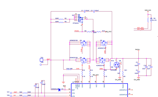
The customer design with BQ40Z50, 4S1P battery pack, fully charged 17.6V.
They use the 4-axis motor with blades to output the maximum speed and then quickly reduce the speed, the system will recover immediately after power failure.
a. Before each test, use LT_RESET to clear the Lifetimes data, test the above operations, check the Lifetimes data after the test, and there is no relevant protection data;

b. Short circuit CHG-FET, DSG-FET (mos is not controlled by fuel gauge CHG, DSG), test the above operations, the system does not appear power failure;

It is now suspected that the BQ40Z50-R3 may have reset under the counter electromotive force.

Attached the .gg file and schematic.
Please give some suggestions.
Thanks
Star
