This thread has been locked.

If you have a related question, please click the "Ask a related question" button in the top right corner. The newly created question will be automatically linked to this question.

TPS7H5001-SP: Glitch in SIMPLIS model PWM output duty cycle when transitioning out of COMP saturating high (>2V)

Part Number: TPS7H5001-SP


I'm seeing some strange behavior from the SIMPLIS model when I sweep the COMP voltage over the full range (for example, applying a slow low-amplitude ~150Hz triangle wave voltage across VSENSE about its nominal center point, and loading COMP only with a resistor to convert current to voltage + a 1pF capacitor to set initial conditions). What happens is that as the COMP voltage slowly rises up above the saturation point of about 2V, the PWM outputs (OUTA, SRA, etc.) suddenly glitch their duty cycle from near-max (which would be expected with COMP at this high voltage) to (max-50%). So when DCL is grounded setting max D to 50%, the output OUTA glitches to the minimum ON time (despite COMP continuing to increase slowly above 2V) and continues to do this across several switching cycles until COMP reaches a slightly higher amplitude (2V + some fraction of a V, exact amount depends on switching freq for some reason). If I pull up DCL increasing the max duty cycle to 100%, the output OUTA glitches down to 50%. The exact COMP voltage points where this glitch starts and ends varies somewhat with switching frequency, as does the length of the glitch pulse, but in general a doubling of the switching frequency doubles the time duration of the glitch.

I've been over the datasheet several times and haven't found any reference to this behavior being expected for the device, so wanted to reach out to see if this is indeed expected, or if this should be taken to be an error in the model. 

Supporting screenshots:

PWM connections (no loads on OUTA or SRA)

Slow triangle modulation of PWM_SENSE input 

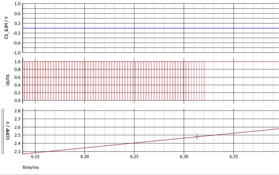
SIMPLIS sim results (Fsync=750kHz, DCL grounded --> Dmax 50%) showing first a zoomed out view of the main PWM voltage waveforms, which at this zoomed out view seem to be behaving just fine, but then below I zoom into one of the glitch regions about 2/3 of the way through the sim when the triangle modulation of the COMP pin creeps above 2V, then reverses and drops below again. I've circled the 2 regions in this bottom plot where an unexpected glitch of OUTA (and SRA if you look closely) occurs. 

  • Hey Brian,

    My initial thoughts having tested the device by forcing comp before is this is a bug with the model
    It might be helpful to test the model a bit closer to the actual application.

    Having a SS capacitor and RSC resistor would be beneficial to the internal timing circuits in the model
    You can also inject the ramp by having RSC equal to 10-20 kOhms instead of injecting it through CS_ILIM

    Are you able to provide your full schematic?

    Thanks,
    Daniel

  • Thanks. I adjusted my model to bias SS from a pre-charged cap rather than pulling high through a resistor but did not observe any difference in behavior. I had actually done my initial modeling with a RSC-based ramp but observed other effects in addition to the spike/pulse behavior I had described. I moved to the CS_ILIM voltage ramp approach because it was difficult to observe exactly what was going on with the internal slope compensation and I had had a theory that there was something off with the slope compensation that was causing both effects. 

    Went back to a ramp based on the FAQ you wrote for emulating voltage-mode control (I get 80kOhms though not 10-20kOhms if I do the calculation in that app note for Fsw=375kHz, so let me know if I'm missing something). When I do that and ground the CS_ILIM pin I still get a similar glitch to what I had described earlier, but I also get a 2nd strange behavior which is that when the COMP pin goes well above 2V and then comes back down again, the OUTA duty cycle stays at 100% for far longer than it should just from looking at the COMP value (for CS_ILIM=0V OUTA stays railed high until COMP ramps all the way down to about 1.36V). I tried varying RSC and the DC voltage applied to CS_ILIM and while it affects the waveform shape somewhat I was not able to find any combination of these two parameters that caused the strange behaviors to disappear and for the model to behave the way I would expect from the datasheet. 

    For the waveforms below I am once again back to Dmax=100% duty cycle which shows this second issue more clearly (but to be clear it still happens at Dmax=50%). Both are snapshots from the same sim run, which is once again applying a slow modulation to VSENSE which then gets applied to COMP via the OTA and a simple 100kOhm resistor to convert the current output of the OTA into a voltage.

    To your last point, happy to share the schematic but would prefer to do so offline if possible. Let me know. 

  • Hey Brian,

    I messaged your email you used for making your account.
    We can take this offline.

    Thanks,
    Daniel