This thread has been locked.

If you have a related question, please click the "Ask a related question" button in the top right corner. The newly created question will be automatically linked to this question.

TPS92630-Q1: about the TPS92630 issue

Part Number: TPS92630-Q1

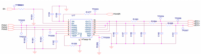
when i use the TPS92630 IC,  three channel apply ,refer to the following circuit:

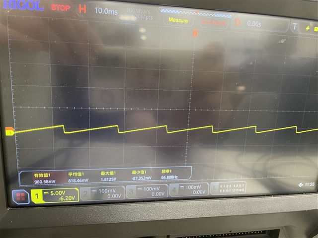
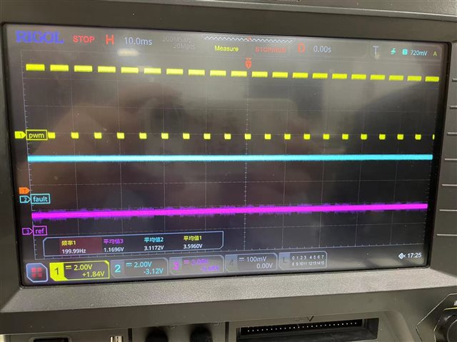
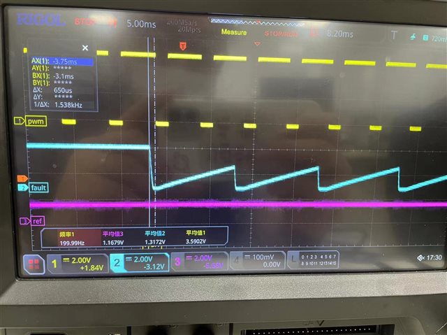
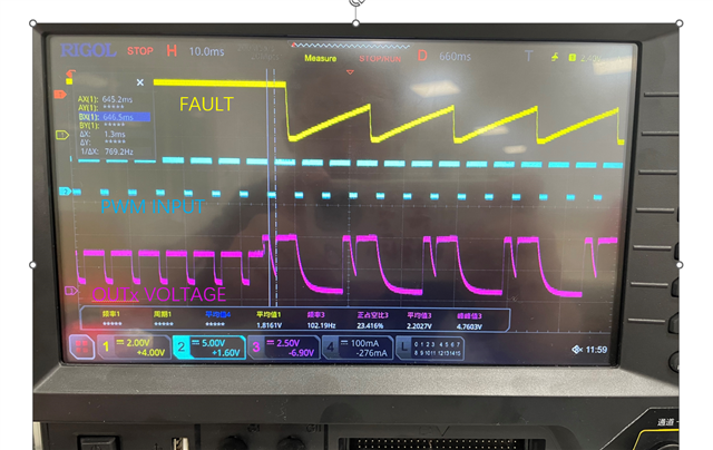
PWM signal generated by MCU, IC driven three way LED,  But when I disconnected one channel LED, the remaining two channel LEDs began to flash,

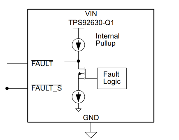
Why is this happening?During this period, PWM1,2,3 has been continuously inputted ,  i think  I connect pins 6 and 7 together, when one LED goes out, the other two LEDs should go out together,

Why do I disconnect one channel LED and the other two channel LEDs flash instead of going out ? could  you explain it to me ? 

thank you~

  • Thank you for your questions.  Our experts in China are on holiday this week.  Please expect delay in response.

    Best regards,

    Dave

  • hello.  could you reply to me by Experts from the United States, because i am in a hurry , and I used English

  • I apologize for the delay, but the design and application support for these products are from our team in China.  They will respond as soon as possible once they return from holiday.

  • OK ,Thank you  ,i got it 

  • Could you share test waveforms? 

    You may capture EN/FAULT/PWM/VIN/VOUT/REF pins 

  • 我觉得我发现问题所在了,但是没有想明白为什么会这样?  我只测了FAULT引脚的波形,我FAULT 引脚对地加了一个100NF的电容,如果取消这个电容,就会恢复正常

    ...

  • could you help explain this refer to the following picture?

  • Sorry that I can't guess with just fault pin shows. 

    It might because fault pin ramp up slower due to charge of capacitor. 

  • ok,i will   capture  En Pwm fault,and ref waveforms …

  • hello, I capture PWM, fault,and ref waveforms  ,  this picture is the normal waveform

    the pwm input average voltage is 3.6V,(max 5V, duty 73.6%) fault pin average voltage is 3.1V,ref pin average voltage is about 1.2v.

    when i cut off one channel LED, The remaining two LED channels begin to shake,refer to the following picture 

    there is no change of the PWM and ref pin ,only the fault  pin changed ,   i think when i cut off the one channel LED, the fault will pull down  to GND,

    but i do not understand  why the fault pin voltage pull up again? could you help explain this  ? 

    i also checked the datasheet refer to the following picture ,, i think when the IC detected the LED open FAULT ,the MOS will open ,and the FAUTL will pull dowm to GND, if the fault pin pull up again , The only reason is that the MOS  is turned off again,why the mos turn off again? Is there any special logic in this? please help! if you need any other information , my pleasure!


  • It shows that fault PIN voltage ramps up slowly due to the capacitor and discharges again before it raise to > 2V (which is logic threshold voltage). As chip monitor Fault pin status, this makes the device always can't trigger 7 PWM cycle fault detection. With removing of the capacitor, Fault pin can quickly ramp up to 5V when PWM dimming controls, thus, triggers 7 PWM cycle fault detection.  

  • i do not understand 

  • i do not think so....  When all LEDs are working properly, the Fault PIN remains high

    when i cut off one channel.... Only then will the following waveform appear

    when detected the LED open , the fault pin go down.... 

    I don't understand what you're saying

  • TPS92630 fault detection is quite complicated. Just pay attention not put large capacitor on Fault pin, which might affect fault detection. I will provide you more info about it later

  • More information for your reference. As mentioned above, you may capture FAULT/PWM/VIN/VOUTx together with Fault falling edge trigged to see difference w/wo large capacitor if you are interested in it.  

     Open/Short to Battery fault mechanism runs both two detection methods at the same time

              ①one PWM on-time is more than 2ms

              ②seven continuous PWM duty cycles

    Fault status update for the second method Fault is judged/latched and status is updated at the PWM falling edge.

    With large capacitor, fault pin is still lower than 0.7V for long time after PWM falling edge, which disables all channels output during the period. 

    For example, in the picture you shown, device outx channel is off as Fault is still low for the PWM cycle following OPEN fault detected.  


    This means seven continuous PWM duty cycles detection always fail and it can't turn off all normal channels.  

  • Hello, First of all, thank you very much for your explanation, but I think I may not have clarified some parameters。

    for example ,about the following parameter.

    What does VIL mean? and what does VIH mean ? 

    ①My understanding is that when there is no fault, the voltage of the Fault pin is higher than 2V, and when a fault is detected, the voltage of the pin is lower than 0.7V, Is my understanding correct? 

    ②But from your description, I guess that when the voltage of the Fault pin is lower than 0.7V, 7 PWM detection cycles will not be triggered. Only when the voltage of the Fault pin is higher than 2V will it be triggered.  Is my understanding correct?

    and i have another one question about the two fault detection methods:

     ①one PWM on-time is more than 2ms

     ②seven continuous PWM duty cycles

    from your description, i think Both detection methods exist simultaneously, This may depend on the time the fault occurred。

    If the fault occurs within the PWM on time and the time is sufficient for 2ms,so the ① apply。

    If the fault happens to occur within the PWM on time and the time is less than 2ms or Or the fault occurs within the PWM OFF time,so the ② apply , Is my understanding correct?

    thank you 

    best regards 

  • For the first question, Fault pin has two features: 

    1. Logic output: When device detected error, it will try to pull down fault pin with typ. 750uA current. If fault recovers, there is weak pullup current typ. 8uA trying to pull up fault pin. Actual output voltage depends on fault pin external circuit. 


    2. Logic input: Monitor Fault pin status as kind of one-fail-all-fail function. If Fault pin is low than 0.7V, then all device outputs turn off, if Fault pin is higher than 2V, then all device outputs enables and turn on if normally. see below and also Figure 19 fault-line bus connection. 

    For second question, ① & ② both exists. So if one PWM on-time is more than 2ms, fault detection pulls fault down. Once PWM fall to 0, fault Pin starts pulling up with weak pullup current and detects during next PWM cycle. You can see from the waveform that fault pin is pulled down every time after it rise up and 2ms on time is detected(open detection).


  • helllo ,sorry,i am late, thanks for your explain,i think i have got it,

    capture an new waveforms refer to the following picture, FAULT PIN , PWM INPUT signal  and OUTx voltage(open channel) 

    Based on your explanation, let me explain my understanding:

    first of all ,when one channel LED open ,  if the fault occurs within the PWM ON time and the PWM ON time is less than 2ms or PWM OFF period,No fault detection will be conducted during this cycle, and detection will begin in the next PWM cycle,Within this PWM cycle, after 2ms,the fault pin will pull down ,When the PWM low level arrives, the fault will be pulled up ,And when the PWM high level arrives,At this point, fault detection begins(after 2ms fault pull down) After 7 PWM cycles, due to an LED open  fault, the FAULT PIN is permanently pulled down.

    The situation described above belongs to a normal situation where the fault pin does not have a large capacitance。

    but But due to the addition of a 100NF capacitor at the FAULT pin, When PWM is at low level, the voltage of the fault pin increases slowly,During this PWM cycle, the voltage cannot reach more than 2V,So in order to complete the detection of 7 PWM cycles, the fault pin of the chip will be continuously pulled up internally,After several PWM cycles,the voltage of the Fault pin is higher than 2V, Start fault detection at this point After 2 ms, the fault is detected and then pulled down again,(Finally, the following fault pin waveform appeared)

    In the following figure, After the first pull-down of the fault pin pin,it can be seen that after 2 PWM cycles, the fault was detected and the pull-down operation was carried out after the fault was raised.  Is my understanding correct? 

  • Yes, it is correct

  • OK,I GOT it ,thank you very much, and i have another question about the circuit , If I want to achieve one channel LED open  and the other two LEDs still working properly, i think i should pull up the fault PIN externally, I noticed a sentence in the chip datasheet:

    It is necessary to configure sufficiently strong pull-up to overrride pull-down,How should I design it ? 

    one question:

    two question:

     i checked the Linear LED Driver Reference Design for Automotive Lighting Applications:

    i found it  recommends using a 100NF capacitor for debounce protection, what is  debounce protection ? why ? 

    could I understand that it is only recommended to add 100nf capacitance when there is external pull-up? if there is no external pull-up, we should cannel the CAP,right ?

  • The capacitor is used for de-bounce protection when connected through a jumper. If no jumper used or jumper is always there, the capacitor is no needed. 

  • OK, i got it ,thank you for your help, I am very grateful for this