This thread has been locked.

If you have a related question, please click the "Ask a related question" button in the top right corner. The newly created question will be automatically linked to this question.

BQ2970: Charger Detection not functioning while combine with BQ25887RGER

Part Number: BQ2970
Other Parts Discussed in Thread: BQ25887

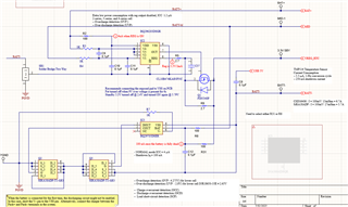
The BQ29705 battery protection circuit and BQ25887RGER battery charger are both functioning properly under normal 500mA current. However, when the battery is fully discharged, the discharge MOSFET fails to turn on as it should when the charger cable is connected via the charger detection circuit. It remains off, and I am still unable to resolve the conflict between the two components.

To address this issue, I added a 0.1uF capacitor between the battery ground and USB_BUS, which generates a negative voltage on the battery ground with respect to the charger ground. This solution works most of the time, but there are still occasional instances where the discharge MOSFET fails to enable again when the battery is fully dead.

Please note that R9 and R31 are DNP. The battery pack is a 2-cell, 7.4V pack, and the BQ29705 is being powered from the middle pin of the battery pack

  • Hello Salinda,

    It could be that the battery voltage is still not high enough to enable the DSG FET. Charging can still occur even if the DSG FET is off due to the parasitic body-diode of the BQ29705. The battery must be charged to an enough voltage and the grounds need to be within the specified values to enable the DSG FET. All conditions to enable the DSG FET from UVP are listed in Section 9.4.3 Over-Discharge Status of the datasheet. What are your battery voltage and charger voltage?

    Best Regards,

    Luis Hernandez Salomon

  • HI Luis,

    Highly appreciate your suggestion and assistance.

    The battery pack consists of two lithium-ion INR18650-35E batteries connected in series, with a nominal voltage of 7.4V. The BQ29705 battery protection IC is powered from the middle pin of the battery pack.

    When the voltage of the lower battery drops below 2.5V, the discharge MOSFET is turned off as described in Section 9.4.3 of the datasheet on Over-Discharge Status. Once a charger is connected, a small current flows through the body diode of the DSG FET, and the charger detection circuit can detect this condition by sensing -0.7V. When the voltage detected at the V- pin is higher than -0.7V, the device releases the over-discharge state and allows the DOUT pin to go high, turning on the discharge FET once the battery voltage exceeds the over-discharge detection release hysteresis voltage (VUVP +Hys).

    It's important to note that this can happen even if the battery voltage is higher than the 2.5V UVP voltage when the battery is connected to the circuit for the first time. In this case, once the charger is plugged in, the charger detection circuit should detect and turn on the DSG FET as mentioned in the datasheet.

    The battery pack is charged by the BQ25887RGER battery charger using a 5V USB supply. When the USB charger port is connected, the DSG FET is continuously turned off, preventing the charging process from initiating. Here im attaching the BQ25887RGER charger circuit for your reference as well.

    Best Regards

    Salinda Tennakoon

  • Hello Salinda,

    This is a very odd configuration, we have not seen someone use this on the middle of a battery pack. Typically this part is used as a single cell protector.

    Even if the DSG FET is turning-off, charging should still be possible due to the body-diode of the FET. 

    It's important to note that this can happen even if the battery voltage is higher than the 2.5V UVP voltage when the battery is connected to the circuit for the first time. In this case, once the charger is plugged in, the charger detection circuit should detect and turn on the DSG FET as mentioned in the datasheet.

    Correct, this usually happens only when the battery is just connected. In UV mode the part will require the a charger and the cell voltage to be above UVP + Hysteresis for the DSG FET to turn on. 

    If the DSG FET is suddenly turning-off, could some of the protections being triggered? Have you checked if any protections could be triggered? 

    If the top cell is removed, do issues still occur?

    Have a good weekend Slight smile.

    Best Regards,

    Luis Hernandez Salomon

  • Hi Luis,

    Thank you for your response and for providing insights into the unusual configuration I have implemented. I understand that using this particular setup in the middle of a battery pack is uncommon, as this component is typically employed as a single cell protector.

    Regarding your comment on the charging capability despite the DSG FET turning off, I am aware that charging should still be possible due to the body-diode of the FET.

    To address the concerns raised, I would like to provide some additional information. Since I was unable to find a suitable TI 2-cell battery protection IC, I decided to combine the BQ296203DSGR, which offers overcharge detection (OVP) and over-discharge detection (UVP) for both cells, with the BQ29705DSER, which provides charge overcurrent detection (OCC), discharge overcurrent detection (OCD), and load short-circuit detection (SCP). The BQ29705DSER is controlled by the BQ296203DSGR through a P-MOSFET.

    During testing, all the modes mentioned above were successfully validated, and they operated as intended. However, I discovered that the charger detection circuit was not functioning correctly when paired with the BQ29705DSER. This occurred because the BQ296203DSGR would disconnect the 3.3V power supply to the BQ29705DSER when the battery became completely discharged. To overcome this issue, I made the decision to power the BQ29705DSER by engaging R31 instead of R8.

    I conducted further tests on the BQ29705DSER's standalone functionality using a single cell, and the results were as follows:

    1. When the battery voltage exceeded 2.6V, both MOSFETs operated correctly and turned on as expected.
    2. When the battery voltage dropped below 2.6V, the DSG FET did not turn on, but the battery could still charge slowly through the parasitic body-diode of the DSG FET. Once the battery voltage reached 2.6V, the DSG FET turned on as intended.

    The main issue arises when the BQ29705DSER is combined with the BQ25887RGER. The BQ25887RGER initiates trickle charging, but this trickle charge is insufficient to charge the battery through the parasitic body-diode of the DSG FET, preventing the voltage from reaching 2.6V.

    I have thoroughly examined the situation, and I can confirm that none of the other protections are triggering, and the DSG FET is not turning on at all due to the aforementioned reason.

    I would greatly appreciate your guidance and assistance in resolving this issue. If you require any additional information or would like me to perform further tests, please let me know.

    Thank you for your attention and support. I look forward to your response.

    Best regards,

    Salinda

  • Hello Salinda,

    I appreciate the very detailed explanation and your findings! Now I have a clearer picture of what is going on. 

    If I am understanding correctly, the BQ25887 not able to provide trickle charging due to the body-diode of the DSG FET not being able to become forward biased. is this the case? If so, then maybe you could try adding a Schottky diode across the DSG FET to see if they are able to become forward biased to charge the battery to the right battery voltage. 

    Best Regards,

    Luis Hernandez Salomon