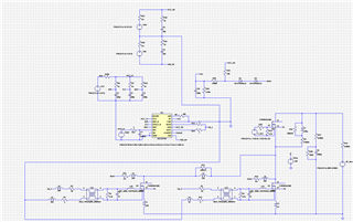
I am using the UCC21710 spice model to set up the double pulse test in LTspice. The voltage at the OC pin goes negative during the turn-on transient. But the datasheet waveform doesn't match the simulation (i.e., negative voltage during turn-on transient) at the OC pin. Is there anything wrong with the setup done in LTspice (shown in the figure below), or does the UCC21710 model require some modifications?
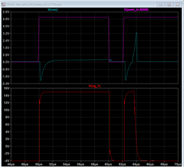
Pink waveform - Input to UCC21710
Light blue - Voltage at OC pin
Red - Output of the UCC21710