This thread has been locked.

If you have a related question, please click the "Ask a related question" button in the top right corner. The newly created question will be automatically linked to this question.

BQ76952EVM: BQ76952 can not charge

Part Number: BQ76952EVM
Other Parts Discussed in Thread: BQSTUDIO, BQ76952

Hi

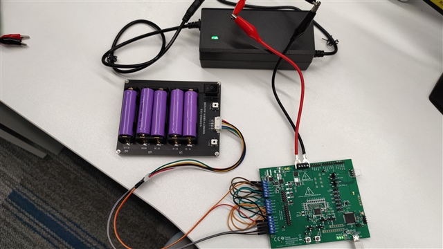
The customer test with BQ76952EVM. In CHGTEST and DSGTEST mode, the charge and discharge switch is turned on.

1. When connected to an electronic load to discharge, the voltage drop of cell16 -> pack+ is 5.17V, the resistance of pack+ -> cell16 terminal is 0 ohms, the resistance can not be measured from cell16 to pack+, and it can be discharged normally with a discharge current of 0.5A.

2. Turn off the electronic load, stop the discharge, measure the resistance of the pack+ -> cell16 terminal is 0.64 kohm, and the resistance cannot be measured from cell16 to pack+

3. After connecting the positive and negative poles of the charger, the voltage drop of cell16 -> pack+ is 4.25V, and the resistance of pack+ -> cell16 terminal cannot be measured, and the resistance of cell16 -> pack+ is 0 ohms; it cannot be charged, and the current is 0.

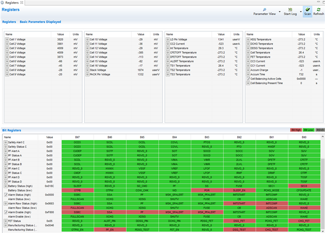
Screenshot during discharge:

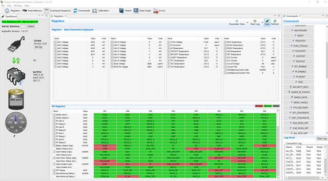
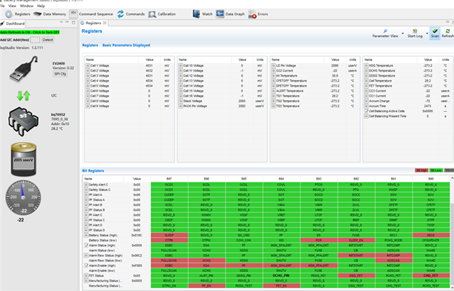
The screenshot when connecting the charger is as follows:

Then turn off the test mode, turn on FET_EN, and then click ALL_FETS_ON, DSG_FET is turned on, but CHG_FET is not turned on. After the electronic load is connected, the CHG_FET is turned on again.

At this time, the opening and closing of the CHG_FET is related to whether it enters SLEEP. At this time, it can be discharged normally. Then connect the charger, no current. The CHG_FET turns on and turns off sometimes, probably due to inaccurate current measurement, even when the pack is disconnected, the measured current jumps from -7mA to -249mA, and is 0 most of the time.

The screenshot 1 when connecting the charger is as follows:

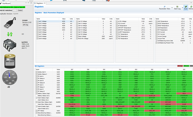
The screenshot 2 when connecting the charger is as follows:

Note: In the above process, no protection occurs.

Waiting for your reply.

Thanks

Star

  • Hi Star, 

    It is a bit hard to follow as it sound looks like multiple test cases.

    Could you please go through each test case on what the set-up is for each area of concern?

    There was also a doubt if there was in-fact a case where both the e-load and charger were attached at the same time, could you please clarify? 

    Best, 

    -Luis Torres

  • HI,

    First of all, the e- load and charger are not connected to the  PACK at the same time. The specific problem is that when CHGFET and DSGFET are turned on at the same time, the e-load connected to the PACK can discharge normally, but the charger(21V) cannot work when connecting to the PACK. Both CHGFET and DSGFET are turned on throughout the process, and no protection is generated. Normal discharge and failure to charge are judged by the measured value of the current. (The five lithium batteries and six terminals between BAT- and CELL5 were connected using DuPont cables, and the rest of the terminals were shorted using DuPont cables.)  So,can you give me some advices to solve this problem? Thank you.

    Best,

    -Lu Shenglin

  • Hi Lu, 

    Let's clarify some of the above test cases in order to better support you. 

    • On here, when you said the resistance to pack+ to cell16 is 0 ohms, but cannot be measured, do you mean they are shorted together? 
    1. When connected to an electronic load to discharge, the voltage drop of cell16 -> pack+ is 5.17V, the resistance of pack+ -> cell16 terminal is 0 ohms, the resistance can not be measured from cell16 to pack+, and it can be discharged normally with a discharge current of 0.5A.
    • How can you measure resistance from PACK+ to CELL16, but not from CELL16 to PACK+? Also, how are you measuring resistance (4-wire meter, V/I calculation)?
    2. Turn off the electronic load, stop the discharge, measure the resistance of the pack+ -> cell16 terminal is 0.64 kohm, and the resistance cannot be measured from cell16 to pack+
    • How is the charger connected? Is this drop due to an inrush current or is a consistent drop while charging? Is the 0.5A load disconnected at this time?
    • What current is 0? The one measured by the BQ or measured externally? If the current is indeed 0A and no load is connected, where is the energy lost going? Is there something else connected to the battery? 
    3. After connecting the positive and negative poles of the charger, the voltage drop of cell16 -> pack+ is 4.25V, and the resistance of pack+ -> cell16 terminal cannot be measured, and the resistance of cell16 -> pack+ is 0 ohms; it cannot be charged, and the current is 0.
    • Can you clarify when is the current 0mA vs when is not? Do you have a scope capture of what happens at charger plugged in? 

    Then turn off the test mode, turn on FET_EN, and then click ALL_FETS_ON, DSG_FET is turned on, but CHG_FET is not turned on. After the electronic load is connected, the CHG_FET is turned on again.

    At this time, the opening and closing of the CHG_FET is related to whether it enters SLEEP. At this time, it can be discharged normally. Then connect the charger, no current. The CHG_FET turns on and turns off sometimes, probably due to inaccurate current measurement, even when the pack is disconnected, the measured current jumps from -7mA to -249mA, and is 0 most of the time.

    • Also, just to confirm this is all with the EVM board? Have you tried a different unit/evm? And can you take a picture of your connections so we can look at jumpers and make sure the hardware is configured properly. 

    Best regards, 

    Arelis Guerrero 

  • Hi Arelis

    Thanks for your reply.

    1,  Please ignore

    2, The charger is connected to the positive and negative terminals of the PACK of the EVM board; after connecting the charger, turn on CHGTEST and DSGTEST (FET_ENABLE is off), the current display on the BQSTUDIO interface is always 0; there is nothing else on the battery. The following figure shows the line connection. (Shunt jumpers on cell1 to cell16 are all removed, I2C jumpers are fine)

    The circuit of the battery box is as follows: (the battery pack and the EVM board are only connected to CELL0, CELL1, CELL2, CELL3, CELL4, and CELL5)

    3, The current is 0mA, which means that after plugging in the charger and turning on the charge and discharge switch, the current display on the BQSTUDIO is always 0 (the data is always updated according to the default cycle).

    The customer doesn't have any other EVM boards on my side.

    They wondered if it was a problem with the FET, I measured the voltage across the FET in different states:

    When connected to electronic load:

    CHG=1,DSG=1时,UFE=4.56V, UFD=-0.256V;

    CHG=1,DSG=0时,UFE=19.27V, UFD=18.50V;

    When connected to the charger: 

    CHG=0,DSG=1,UBA=1.12V, UBC=1.48V;

    CHG=1,DSG=1,UBA=1.11V, UBC=1.46V;

    Is this normal? But in the same circuit, the discharge is normal, but the charging is not normal (the charger and the electronic load are not connected at the same time)

    Waiting for your reply.

    Thanks

    Star

  • Hi Arelis 

    Update the test :

    The battery voltage is 19.77V.

    When connected to an electronic load for discharge: CHG=1, DSG=1,

    UD = 18.38V,  UE = 13.63V   UF = 18.16V,

    UC = 18.60V, UA = 18.74V   UB = 18.11V

    When connect the charger:CHG=1,DSG=1,

    UD = 20.81V,  UE = 21.21V   UF = 20.87V,

    UC = 1918..43V, UA = 19.75V   UB = 20.87V。

    When discharging, UD>UE, so the discharged MOS can be turned on normally;

    When charging, UC<UA, the FET is not actually turned on, I checked the register settings, Chg Pump Control is set to 01, the charge pump is enabled, but the voltage of CHG is lower than the battery voltage, so the CHG MOS failed to turn on.

    Why the CHG MOS can not turn on? Why the DSG MOS  has 4.53V drop during normal discharge?

    Waiting for your reply.

    Thanks

    Star

  • Hello Star,

    What is the CP1 voltage, this should be about ~11-V above the battery voltage. If this voltage is abnormal, then the drivers will likely not be able to drive the FETs properly.

    For these tests are you using the the FET_TEST commands (When FET_EN = 0) ? If so, how do the registers look when the FETs are enabled? DSG_TEST/CHG_TEST should both be SET if using these.

    For autonomous mode (FET_EN = 1), the CHG FET will turn-off during sleep mode by default. For this testing it may be good to disable sleep mode by using the sleep disable command in the Commands window of bqStudio. You can also make the CHG FET stay on during SLEEP mode by changing the settings.

    Can you also share your .gg settings?

    Best Regards,

    Luis Hernandez Salomon

  • Hi Luis 

    Thanks for your help.

    Attached the .gg file.

    8420.data memory.gg.csv

    The register setting as below:

    FET Options = 0x0d,  Chg Pump Control = 0x01

    When setting CHGTEST=1 and DSGTEST=1, the voltage of TP3 is 19.38V, and the voltage of TP2 is 19.38V, that is, there is no difference between the two ends of the C3.

    When FET_ENABLE, click ALLFETON, and click SLEEP DISABLE. At this time, the Registers shows that DSG_FET and CHG_FET are turned on, but the voltage of TP3 is still 19.38V, and the voltage of TP2 is 19.38V. 

    Does the setting correct? However, the charge pump has been set to be enabled. At this time, the voltage of TP3 should be 11V higher than the battery pack voltage, but the charge pump is not charging in the actual situation.

    Please give some suggestions.

    Thanks

    Star

  • Hello Star,

    I tested their settings and it worked from my side.

    TP3 should be ~11-V higher than TP2 if the charge-pump is enabled, if this is not the case, either the charge-pump is being drained somehow (too high of a load on the DSG/CHG pins), or the IC may be damaged.

    Can you tried replacing the IC and see if the issue is fixed?

    Best Regards,

    Luis Hernandez Salomon

  • Hi Luis

    Thanks for your help.

    The customer replace the BQ76952, they use a 32V power supply to simulate the total voltage of 10 cells (the remaining six cells are shorted);

    Then turn on BQSTUDIO, turn on FET_ENABLE, and turn on SLEEP_DISABLE, the PACK is not connected, and the rest of the configurations are default configurations.

    The ground voltage of TP3 is 42V, but it smells burnt soon, and the voltage of TP3 drops rapidly during the test; after the power is cut off immediately, the resistance across the charge pump C3 can be measured to be 12.1 ohm.

    After the BQ76952 is burned out, the voltage can be displayed normally. In the case of closing the CHGFET and DSGFET registers, the measured voltage of the CHG pin of Q8 is about 30V, and the measured voltage of the DSG pin of Q9 is 0V. 

    Is the BQ damage related to the DSG pin?

    Waiting for your reply.

    Thanks

    Star

  • Hello Star,

    This is strange. How are they connecting the power supply? Are there any shorts on the board?

    There should be no reason for the capacitor to be shorted nor the IC to become damaged unless there is a short somewhere.

    Best Regards,

    Luis Hernandez Salomon

  • Hi Luis

    Thanks for your reply.

    The customer check the EVM and find the D4 zener next to the CHGFET is burned out.

    If the reverse voltage between the two ends of D4 is higher than 16V, it will be burned out, and if the voltage of CP1 pin is higher than the voltage of the battery pack voltage 15V, it will be burned out.

    So the final reason is that the charging of the charge pump exceeds the control switch in CP1 and D4. withstand voltage.

    What controls the charging of the charge pump, and how to prevent the charge pump from charging beyond the set value?

    Waiting for your reply.

    Thanks

    Star

  • Hello Star, 

    The D4 Zener is placed specifically to protect the CHG FET from voltages above 16-V. This typically only happens during events of large transients, like a short-circuit event. 

    During normal operation there will always be a ~11-V voltage across the D4 Zener, when the part is OFF the voltage across the diode would be ~0-V. So typically the Zener would not be exposed to a voltage above 16-V.

    The part will always control the charge-pump in relation to the BAT voltage. So it will always be ~11-V above the battery voltage. 

    Best Regards,

    Luis Hernandez Salomon