This thread has been locked.

If you have a related question, please click the "Ask a related question" button in the top right corner. The newly created question will be automatically linked to this question.

LP5891-Q1: DS-PWM details on number of Segment and how it drives LEDs

Part Number: LP5891-Q1
Other Parts Discussed in Thread: LP5891, LP5890, LP5861

Hi everyone,

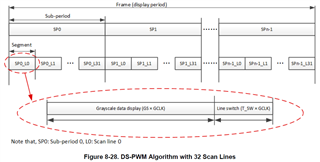
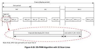
Based on the datasheet, LP5891-Q1 is using DS-PWM Algorithm where one frame will be divided into sub-periods and each sub-periods will be divided into 32 segments. The number of sub-periods can be set by FC0 register bit24-22 but how about the number of segments? Can it also be set, or it is fixed with 32 segments?

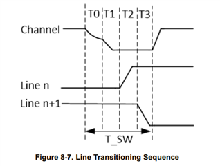
If the answer is that it can be set, what if in a few frames I set only one sub-period and one same segment, will I be able to turn on the scan line in that segment continuously without "OFF" time due to Line Transitioning Sequence?  

Also, related to scan lines, when they are turned on, does the corresponding constant-current output always drive LEDs using PWM signal (hence the name DS-PWMSweat smile)? Or can it be set to drive LEDs just using HIGH logic signal (like 100% duty cycle)?

Thank you in advance. 

Regards,

Muhammad Adityo

  • Hi Muhammad,

    Question 1:

    DS-PWM is called Dynamic PWM so the sub period number is not fixed. the SUB Period number can be set in FC0 Bit 24-22.

    Question 2:

    Do you means just use one scan line? the sub period number just can be set to 16/32/64/80/96/112/128 and segment length must be larger than 128GCLKs.

    Question 3:

    you can write the PWM value to maximum, so when during the line turning on, the channel will always turn on.

    Could you provide the information about you design(LED Matrix, LED current, pixel pitch, application...) and I can suggest more details about configuration..

    BR

    Monet Xu

  • Hi Monet Xu,

    Thank you for your reply, it gives me some clarity on my confusion. But I am still figuring out how LP5891 really works, so please bear with me and let me revise some of my questions:

    1. Let say, I set the number of sub-periods (SUBP_NUM) to 128 and the number of scan line (SCAN_NUM) to 1. Can I activate scan line 0 for one frame and then activate scan line 1 for another frame?
    2. With the same SUBP_NUM and SCAN_NUM in question 1, if I set the output of channels that connected to the activated scan line with maximum PWM value, will those channels always turn on for 128 x Segment Length (without "OFF time" between sub-periods)?

    As for my design, I was aiming to drive 96 LEDs with 8 rows and 12 columns configuration like this diagram:

    The requirements are:

    1. Only one column can be activated at a time with maximum duration of 10 ms.
    2. User can arbitrarily activate any one column at any time.
    3. When a column is activated, up to eight rows can be turned on simultaneously.

    The reason I want to use LP5891 is because this design might be scaled into larger configuration (like 16 rows and 24 columns) in the future.

    Regards,

    Muhammad Adityo

  • Hi Muhammad,

    Let say, I set the number of sub-periods (SUBP_NUM) to 128 and the number of scan line (SCAN_NUM) to 1. Can I activate scan line 0 for one frame and then activate scan line 1 for another frame?

    setting SCAN_NUM to 1 means that the line number is 2. LP5890 has internal SRAM to store the PWM value for each pixel(line, channel), so for frame 1, writing non-zero PWM data to line0 and 0 to line1. for frame 2, writing 0 to line 0 and write  non-zero PWM data to line1.

    With the same SUBP_NUM and SCAN_NUM in question 1, if I set the output of channels that connected to the activated scan line with maximum PWM value, will those channels always turn on for 128 x Segment Length (without "OFF time" between sub-periods)?

    No. LP5891 sets 2 scan lines so as the below figure shows, each frame will divide into SUBP_NUM sub period and each sub period includes 2 segment(one for line0 and another for line1). Since the Line0's pixel data is set to maximum and line1 is set to 0, segment0_L0 will always on but segment _L1 will off so the channels is not always on. but the refresh rate is pretty high so we will see the line0 keeps on and line1 keeps off.

    As for my design, I was aiming to drive 96 LEDs with 8 rows and 12 columns configuration like this diagram:

    I have some questions:

    1. where will use this design?

    2.single color LED or RGB pixel?

    3.average current of each LED and LED VF?

    4....

    for higher current and voltage application, we have another device TLC696x8 which have 16 channels and support max 8 scans. so let me know you spec.

    BR 

    Monet Xu

  • Hi, Monet Xu

    I think I got the general idea how LP5891-Q1 works now, thank you.

    Surely LP5891-Q1 is not fit for my design application. In fact, any IC that uses time-multiplexing scheme will not work for my design. So, I am not sure about TLC696x8 that you suggested.

    As for your question, my design will be used in a device intended as a group of light barriers. All LEDs in that device is Infrared (IR) LEDs with current varies around 3mA to 10mA (dynamically changing on operation). The forward voltage of the IR LEDs is around 1.45V to 1.7V.

    Anyway, can you suggest another ICs with these features:

    • Individual analog dimming for each LED.
    • Does not implement time-multiplexing scheme in driving LEDs matrix, instead it can choose any one LED column to be activated.
    • Able to drive minimum of eight LEDs simultaneously at a time.

    Regards,

    Muhammad Adityo

  • Hi Muhammad ,

    LP5861 is an 18 channel LED driver with 8-bit analog dimming and maximum current is 50mA which may suitable for your application.

    https://www.ti.com/lit/ds/symlink/lp5861.pdf?ts=1683800059937&ref_url=https%253A%252F%252Fwww.ti.com%252Fproduct%252FLP5861%253FkeyMatch%253D%2526tisearch%253Dsearch-everything%2526usecase%253Dpartmatches

    BR

    Monet Xu