Hi,
I have a battery powered low power application. during my device idle mode I get a current consumption of around 40uA. I'm running a test sequence where I:
Power On System -> (Wait 3 seconds -> Enable LED sequence with 2 LP55231 -> wait 3 seconds -> Disable the LP55231 by setting EN pin low -> wait 3 seconds) -> Repeat
below is a screenshot of my power measurements. I've divided into 3 sections:
A: 3 seconds prior to enabling the LED sequence on the lp55231 on startup. (40uA av)
B: 3 seconds LED is running (3.72mA Av)
C: 3 seconds after setting LP55231 EN pin to low (94uA Av)
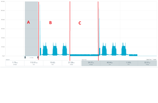
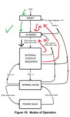
My expectation is that when setting EN to low both LP55231 should enter standby mode and have a current consumption of ~200nA but instead I'm seeing an additional 54uA. I'm convinced it's the LP55231 that is the source of this additional current. if i leave all other parts of my firmware alone and just comment out the function that enables the LEDs i never see the current increase of 54uA.
Any idea why this is happening? Is there anything additional i should be doing beyond just setting the EN pin low?
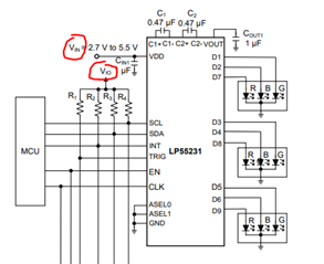
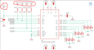
Below are some code excerpts and schematics:
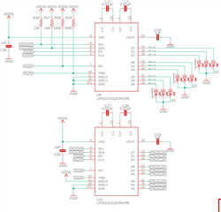
/*******************************************************************************
 * @fn          LedTest
 *
 * @brief       Test the LED
 *
 * @return      None
 ******************************************************************************/
static void LedTest(void)
{
    led_Init();

    // led_test();

    k_sleep(K_MSEC(3000));

    while (true)
    {
        led_run(LED_PROGRAM_AWAIT_PILL_DISPENSE);

        k_sleep(K_MSEC(3000));

        led_stop();

        k_sleep(K_MSEC(3000));
    }
}
bool led_stop(void)
{
    if(lp55231_Disable() == false)
    {
        LOG_ERR("Failed to disable mother device");
        return false;
    }


    return true;
}
bool lp55231_Disable(void)
{
  if (!device_is_ready(led_enable.port))
  {
      LOG_ERR("LED Enable GPIO device is not ready\r\n");
      return false;
  }

  int32_t err = gpio_pin_configure_dt(&led_enable, GPIO_OUTPUT_ACTIVE);
  if (err < 0)
  {
      return false;
  }

  err = gpio_pin_set_dt(&led_enable, 0);
  if (err < 0)
  {
      return false;
  }

  return true;

}


