This thread has been locked.

If you have a related question, please click the "Ask a related question" button in the top right corner. The newly created question will be automatically linked to this question.

LM5177: experimental issue

Part Number: LM5177

Hi TI team,

I have a issue on LM5177.
Base on our design , the test condition as below :
Vin = 52V, Vout = 56V, Iout = 11A,
fs = 300kHz, L = 3.3uH with PSM is enable.

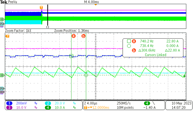
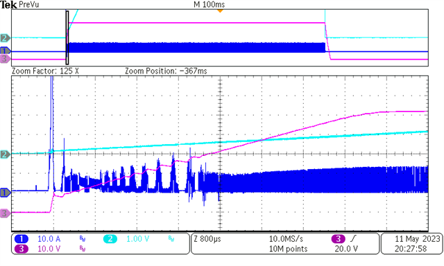
In my opinion, it's operation on boost mode and the buck upper arm MOSFET "Q1" are permanently on, but we found that Q1 turning off randomly then it cause the inductor current drop steeply.

CH1: VDS of boost lower arm MOSFET, CH2: Comp,
CH3: Vout(with 50V offset), CH4: Inductor current
(We have tested Q1's vgs, but it is not shown on the picture.)

What do you think about this issue?
Thanks.

  • Hi Marshall,

    thank you for using the E2E fourm.

    Can you let me know which device version you have - the marking on the LM5177.

    Best regards,

     Stefan

  • Hi Stefan,

    I think it's a new version, there is "31KG4 CK78" marked on LM5177 and I have another quentions about LM5177 show as below:

    When the converter operation with old version "28kG4 CT3R" in steady state, the Comp and inductor current oscillation randomly.
    This abnormal situation disappeared through changing the old version (28kG4 CT3R) to new "31KG4 CK78", does the issue resolve completely even though I change the SI MOSFET to GaN FET(high dv/dt) ?

    Now, I have another design base on EPC GaN, but the soft start mechanism and switching state occur some abnormal situations.

    The soft start occur violent oscillation as below:
    Does it as similar as mentioned before?

    CH1: Comp, CH2: VDS of boost lower arm MOSFET,
    CH3: Vout, CH4: Inductor current

    The abnormal switching state show as below:
    The RT/CT is set as 300kHz, but it appear more than 300kHz switching frequency on inductor current in boost mode and we find the switching noise are reflected on Comp PIN. What do you think about this?

    CH1: Comp, CH2: VDS of buck upper arm MOSFET,
    CH3: Vout, CH4: Inductor current

    thank regards.

  • Hi Marshall,

    the first point you have mentioned is due to a wrong peak detection which can happen in PSM mode. In the RTM silicon this is a function which will be disabled to avoid this behavior.

    On the second issue it looks like a cross talk to some control signals, esp. the COMP pin should be stable in steady state and also during power up the COMP pin does not look OK.

    For startup can you also probe the ATRK/SS pin. 

    How does your compensation look like?

    Best regards,

     Stefan

  • Hi Stefan,

    How do I avoid the wrong peak detection in PSM mode ?
    The current filter parameter of R C is 20ohm + 1nF.
    We have tested both buck and boost mode, the abnormal state only occur at boost mode.

    The noise on comp pin only occur with GaN FET but no SI MOSFET
    The test result with SI MOSFET as below :

    CH1: none, CH2: Comp,
    CH3: Vout, CH4: Inductor current

    The start-up waveform with SS/ATRK PIN as below:

    CH1: Inductor current, CH2: SS/ATRK,
    CH3: Vout, CH4: none

    Here are our compensation circuit.

  • Hi Marshall,

    to ensure it understood right:

    - The first plot of the last email is done with SI MOSFET

    - The 2nd (Startup) is done with GaN or with SI MOSFET again?

    Do you have two different PCBs for GaN and SI MOSFET or have you two with identical footprint?

    Best regards, 

     Stefan

  • Hi Stefan,

    - The first plot of the last email is done with SI MOSFET

    ==> Yes.

    - The 2nd (Startup) is done with GaN or with SI MOSFET again?

    ==> Two startup waveform are done with GaN, the difference between both is soft start time.

    Do you have two different PCBs for GaN and SI MOSFET or have you two with identical footprint?

    ==> The difference of two PCBs is the footprint between GaN and SI MOS.

    Best regards,

  • Hello Marshall,

    We will come back to you early next week.

    Best regards

    Harry

  • Hi Marshall,

    thank you for the details.

    I would like to discuss this with the design team and will come back in 1-2 days.

    To avoid the high current peak at startup can you please increase the Softstart time.

    Can you please also add the additional filter to CSA/CSB as described below (Note: adding this info to the datasheet is just in work)
    esp. C(COMMx)

    Please let me know if this helps to improve this behavior with the GaN FETs

    Best regards,

     Stefan

  • Hi Stefan,

    I can't see the pictures provided by you but we were informed that as below. Is it the same as your?

    However we test start-up again with the CM filter (Ccom = 100pF), there have some improved at SI-MOSFET version but didn't work at GaN version

    And the switching frequency is weird, which is different from our original setting (310kHz change to 150kHz).

    By the way, we found a new problem which was tested before changed the CM filter on CS PIN as below

    The switching frequency is change to more higher randomly in steady state. Does it is about a wrong peak detection problem as you have mentioned before ?

    Test condition :

    Vin = 36V, Vout = 52V, Iout = 13A, RT/CT = 310kHz with SI-MOSFET 

  • Hi Marshall,

    not sure why this pictures do not show up but this is the same info you have.

    The serial resistor RDiff1/2 should be 100Ohm each.

    The C(Diff) can then be calculated with


    C(Comm1/2) should 47pF each.

    For the scope plot above can you let me know the channel assignment.

    It might be good to also review the layout.

    Best regards,

     Stefan