This thread has been locked.

If you have a related question, please click the "Ask a related question" button in the top right corner. The newly created question will be automatically linked to this question.

UCC28780: Startup issues

Part Number: UCC28780

Hi,

I am designing an isolated DC-DC converter using UCC28780. It has some startup problems. The converter is restarting after 6 switching cycles (ULVO cycle reset). Observed that No overcurrent, Overtemperature, brownout,CS pin open/short, HVG overvoltage, thermal shutdown, RDM pin open/short, RTZ open/short  No output overvoltage protection are triggered.  Please let me know what could be the problem. I would appreciate if you could analyze the problem and give a solution

Please also find attached the calculation sheet.

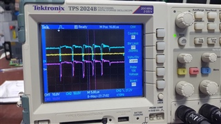
CH1: Vdd, CH2: Low side GaN Vds, CH3: voltage across auxiliary winding

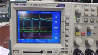
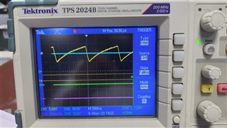
CH1: Vdd, CH2: Low side GaN Vds, CH3: voltage across current sense resistor, Ch4: voltage across secondary winding(scope  probe is connected secondary ground)

UVLO cycle

4760.BOM.xlsx

Calculations Sheet.xlsx

  • Hello Raju, 

    Thank you for your interest in the UCC28780 ACF controller. 

    I think the start-up problem is due to insufficient input voltage.  In other words, the controller has not yet detected the Ivsl(run) level of 365uA in order to continue switching. 

    In your Calculations Sheet, you calculated Rvs1 needs to be ~20.5K with Npa turns ratio of 8 in order to start at 60Vdc input. 
    In your BOM sheet, Rvs1 is listed as 39K and Npa as 7.5, which require Vin to be ~107Vdc in order to start. 
    The scope photo shows Vbulk to be about ~80Vdc.   I suggest that increasing Vin to >107V will allow it to start, as is. 
    And reducing the value of Rvs1 will lower the start threshold, but also adjust Rvs2 accordingly to maintain output OVP.   

    Since the BOM numbers deviate from the design calculator numbers in this regard, there may be other deviations that I haven't searched for, so I'm not sure what will happen once switching continues from the current start-up threshold.  I recommend that you review the BOM values with respect to the design intent to make sure there will be no unwanted over-stresses.  

    Regards,
    Ulrich

  • Hi Ulrich,

    Thank you very much for your reply.

    I will change BOM as per your recommendations and come back to you at the earliest.

    Best Regards,

    Raju Baddipadige

  • Hi Ulrich,

    Primary Turns: 15  
    Secondary Turns: 2  
    Auxiliary Turns: 3  

    Npa is 15/3, It should start at Vin=72V (365uA*39k*15/3) and be tested up to Vin=130V. Observed the Same number(6) of pulses but observed that voltage on RUN pin high throughout UVLO falling cycle(UVLO ON threshold to OFF threshold) and also REF pin voltage is also HIGH.  I will also review BOM. 

    Best Regards,

    Raju Baddipadige

  • Hello Raju, 

    You are right, I made a mistake on reading the Npa ratio.  I apologize for that, and I agree that normally, the switching should continue under your input conditions. 

    Your latest observations are interesting.  Normally, REF will be high as long as VDD is > UVLO(off) threshold, regardless of whether there is a fault of not. So that is okay. 
    However, if a fault is detected that stops switching, the RUN signal should go low.  
    You report that RUN stays high the entire time VDD > UVLO(off), which indicates that no fault has been detected.
    This means something else is apparently interfering with the gate drive of the low-side FET.  

    Am I correct to assume that this issue is related to a previous E2E posting from you about 2 months ago:
    https://e2e.ti.com/support/power-management-group/power-management/f/power-management-forum/1207983/ucc28780-converter-startup-problem 

    Is it possible for you to provide a PDF file of your schematic diagram of this converter? 
    There may be some problem with the way bias power is provided to the GaN Fet that stops the switching after the 5 pulses (not 6), even though PWML continues to be delivered.  Or, there may be some other issue that cannot be detected without reviewing the schematic. 

    Please verify that PWML keeps switching during the entire time that VDD > UVLO(off).    

    Also, in your 2nd scope photo above, the current pulses (CH3, magenta) are unusually "squarish" in shape. I expect them to be triangular and limited to a peak voltage of about 0.28V.  With a minimum target frequency of 300kHz (from pervious E2E post) and 25uH inductance, I wonder if your transformer is a planar design.  If so, there may be high winding capacitance which can distort the primary current with high spikes at the turn-on edge.  Bandwidth limit on the oscilloscope might be hiding these leading edge spikes.  

    Please probe the current signal at the CS pin (across Ccs) using "tip & barrel" probe technique and no BW limit. 

    Regards,
    Ulrich