This thread has been locked.

If you have a related question, please click the "Ask a related question" button in the top right corner. The newly created question will be automatically linked to this question.

UCC28C44: Abnormal behavior when short output

Part Number: UCC28C44

Hi Team,

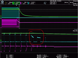
Customer feedback that when short output of UCC28C44, the device will have an abnormal behavior on PWM pulse, which is shown below:

Where CH2: VCC, CH3: Vds, CH4: driver pin

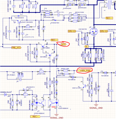
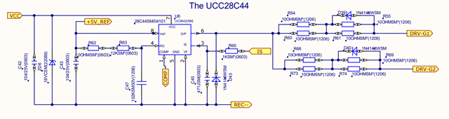
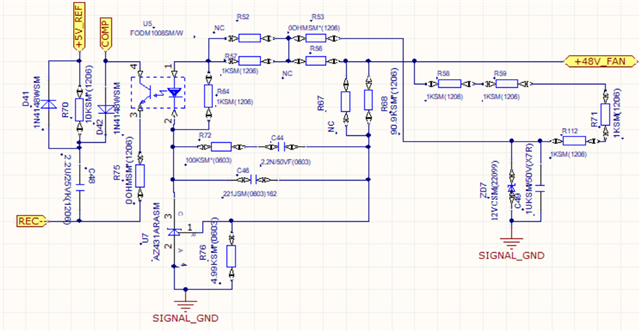
And the schematic is also attached below:

Thanks in advance.

BRs,

Francis

  • Hi,

    Do you mean the VDD UVLO off value not correct? If so, there may be two things to consider.

    (1) If you set up VDD < 8V (say 7.9V), and let it stay there to see if the UVLO off triggered? If it does trigger, then the issue you see is due to the some delay since the UVLO off is tested with steady state.

    (2) Further zoom-in the waveform to see if there is noise bouncing back to the UVLO on, you would need to have the oscilloscope channel with full bandwidth.

  • Hi Hong,

    Do you mean the behavior in red circle is caused by UVLO? Why the duty of PWM will first increase and then decrease? Seems out of control.

    I ask customer test the VREF output(green waveform) and it is high during abnormal behavior, so according to datasheet, the UVLO is not triggered.

    BRs,

    Francis

  • Hi,

    As Vin is decreasing the IC intends to increase duty to maintain the Vout in regulation.

    If VREF still at 5V then the UVLO off not triggered yet, so it looks the delay is the reason - you need to keep VCC at < 8V say 7.9V for a bit time to find if the UVLO off triggered.

    In applications a bit delay is allowed. There should not be a problem in your case as well if you confirm after a small delay the UVLO off triggered at 7.9V.

  • Hi Hong,

    How long time for a bit delay? Because Vin would persistent decrease when customer short for output.

    -This cannot find in datasheet.

    On the other hand, the turn off voltage is 9V on datasheet, which is different with you said:

    BRs,

    Francis

  • Hi,

    It is possible in some 100us but it is not a tested parameter.

    The table you show is for typical for min and max you need to look at page 5 where it shows min off 8V so 7.9V is a good number for you to check in your design.

  • Hi Hong,

    This delay time is too long for customer.

    I have attached the supply power schematic below, it seems a design issue that:

    VCC is powered by the auxiliary winding of the Flyback. When short circuit happens, the output voltage +48V_FAN will naturally drop. When it drops to a certain value, Transistor Q5 will turn off through the control of optocoupler U3. So that is why VCC will drop rapidly.

    Abnormal duty PWM makes the MOSFET works in the amplification area instead of the saturation area, which has a risk of damage.

    Do you have any advice? Please let me know. Thanks.

    BRs,

    Francis

  • Hi,

    You can pull down COMP pin to stop the pulses much faster.

  • Hi Hong,

    So do we have other lower delay time general PWM controller or Flyback PWM controller (OCP, OVP)?

    Due to Ning Tan is in China now, he will talk with you in detail later. Thanks.

    BRs,

    Francis

  • Hi,

    To stop the driver pulses fast, pulling down COMP is a way. VDD UVLO off is not a proper way if you want to stop pulses fast.

  • Hi Hong,

    Thanks for your help, please let us discuss offline.

    BRs,

    Francis