This thread has been locked.
If you have a related question, please click the "Ask a related question" button in the top right corner. The newly created question will be automatically linked to this question.
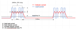
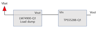
When the load current profile of the TPS55288 used by our company is shown in the picture below, please check with the following inquiries.
(Periodically driven by pulse for a specific time)
1. Please check which of the following values should be based on the current limit setting of ILIM pin: A, B, C, D.
2. Please check the current limit setting by current sensing resistor between ISP & ISN pin which value should be based on A, B, C, and D below.
Hi Chul,
Thanks for reaching out on E2E.
Since the switching frequency of load current is so high as 24MHz, the device could not respond so fast, so the max average output current would be A/2 during 2ms period. And you need to set the output current limit a little higher than 0.5*A_value, and the resistor should be smaller than 50mV/(0.5*A_value)=100mV/(A_value) to leave some margin.
About the ILIM pin, it is the average inductor current limit function, so you need to calculate the max average inductor current at minimum Vin, max Iout. At Buck mode, the average inductor current equals to output current; at Boost mode, the average inductor current equals to input current. As Iout_max=0.5*A_value, so the max average inductor current would be Vout*Iout_max/eff/Vin_min. Also, choose a smaller resistor to leave some margin.
Regards,
Bryce
Thank you for your reply.
It was very helpful.
I would like to ask you one more question.
At the front end of the buck-boost (TPS55288), a load dump IC (LM74900) that turns on/off the Vbat voltage will be used as shown below.
The buck-boost input current is likely to be the load dump output current.
Load dump (LM74900Q1) also needs to set the Overcurrent Limit using ILIM pin.
At this time, we are asking if it is right to choose the current of "C" from the previous waveform
If I have to choose C, I would like to ask if I can choose the input current value in Boost mode.
thank you
Hi Chul,
From my point of view, the overcurrent limit of LM74900 is decided by input current of TPS55288, and the max input current of TPS55288 is at Boost mode, so you can refer to this for calculation.
Regards,
Bryce
Thank you very much Bryce!!^^
I have one more question.
I want to place the EMI Filter, PI filter, between Load dump (LM74900) and Buck-Boost DCDC converter as above question.
- I think the lower the inductor component in the load dump output, the lower the Vspike according to the current change, what do you think?
- Do you think it is right to design the resonance frequency of the left LC of the PI Filter below Fsw/10 to prevent the DCDC converter switching noise from affecting other systems?
- Is it correct that the PI filter electrolytic cap increases the ESR and serves as a damping to reduce the oscillation caused by the inductor?
- Is there a way to supplement a PI filter?
- Please let me know if there is a way for PI filter not to affect DCDC converter.
Hi Chul,
- I think the lower the inductor component in the load dump output, the lower the Vspike according to the current change, what do you think?
Which Vspike do you mean? Generally according to VL=L*di/dt, the smaller inductor value, the lower Vspike is for same di/dt.
- Do you think it is right to design the resonance frequency of the left LC of the PI Filter below Fsw/10 to prevent the DCDC converter switching noise from affecting other systems?
It's a good idea to do that.
- Is it correct that the PI filter electrolytic cap increases the ESR and serves as a damping to reduce the oscillation caused by the inductor?
Do you mean the electrolytic cap is put closed to Buck-Boost side? The ESR could be used for damping, but the voltage ripple would increase due to higher ESR. You may need to put MLCCs to improve the voltage ripple.
- Is there a way to supplement a PI filter?
Do you mean to design a PI filter?
Regards,
Bryce