This thread has been locked.

If you have a related question, please click the "Ask a related question" button in the top right corner. The newly created question will be automatically linked to this question.

BQ25883: Inquiry about simultaneous use of BAT charging and Vsys

Part Number: BQ25883

Hi, TI support team

The customer applied the BQ25883 and created the circuit diagram as follows.

Q. Please review the circuit diagram below.

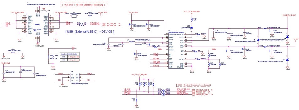
I know that BQ25883 can operate Vsys and BAT charging simultaneously.

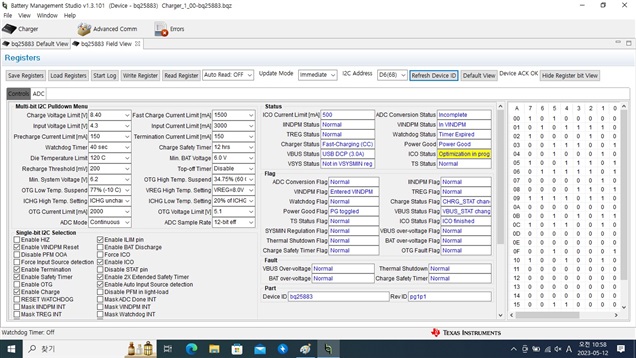
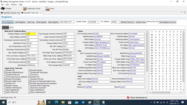
However, when checking the EVM, simultaneous operation is being performed, but the customer's product operates as follows.

- BAT charging is not possible when using Vsys.

- If Vsys is not used, BAT is charged.

Please check what could be the cause of the above behavior.

If a separate setting is required for simultaneous operation, please advise on that part.

Please let us know if you have any information needed to check the cause of simultaneous operation not working.

Thanks.

Regards,

MJ

  • Hi MJ,

    The SYS pin is the output of the boost converter and the battery is another load off of SYS, connected in parallel by the BATFET.   If the input power (VBUS*InputCurrentLimit) is high enough, then both SYS load and battery get power.  If not, the SYS load takes all the input power and, potentially, the battery must supplement the SYS load.  So, the question is, is the input power enough to supply both the SYS load and charge the battery? 

    Regards,

    Jeff

  • HI, Jeff

    Thank you for reply.

    SYS load is using approximately 400mA.

    It is judged to be sufficient to charge the system and battery.

    Even if you use a 5V/2A charger or a 5V/3A charger, the battery is charged only when the product is powered off, and it is not charged when the product is

    powered on and there is a SYS load.

    It seems to be irrelevant to the capacity of the adapter, is that correct?

    And now, the D+/D- port of the BQ25883 is connected to the charging port (type-c connector) in parallel with the MCU.

    How will this affect you?

    Is it a correct circuit to share the same D+/D- port as the MCU?

    Please confirm this part as well.

    Would it be helpful if you could share a register dump?

    Please let me know your e-mail if necessary.

    Thanks.

    Regards,

    MJ

  • Hi MJ,

    The MCU can't use the D+/D- lines for the first 2 seconds after power up.  The D+/D- lines may be setting the charger's input current limit lower than the 2A or 3A source.  A register dump would be helpful.

    Regards,

    Jeff

  • Hi, Jeff

    Since D+/D- is connected to the MCU, can charging and Vsys load not operate at the same time?

    The capacity of the adapter appears to be sufficient.

    Share the register dump as below.

    * Created: Fri May 12 11:00:02 KST 2023
    *
    * Format: Register Name  tab Character,\t  Register Address  tab Character,\t  Hexadecimal register value.
    * BQZ Container: Charger_1_00-bq25883.bqz
    *
    REG00	00	A0
    REG01	01	5E
    REG02	02	84
    REG03	03	39
    REG04	04	22
    REG05	05	9D
    REG06	06	7D
    REG07	07	02
    REG08	08	0D
    REG09	09	F6
    REG0A	0A	00
    REG0B	0B	2B
    REG0C	0C	B2
    REG0D	0D	00
    REG0E	0E	00
    REG0F	0F	21
    REG10	10	92
    REG11	11	00
    REG12	12	00
    REG13	13	00
    REG14	14	00
    REG15	15	30
    REG16	16	02
    REG17	17	00
    REG19	19	00
    REG1B	1B	00
    REG1D	1D	00
    REG1F	1F	00
    REG21	21	00
    REG23	23	00
    REG25	25	19

    The adapter is a 2A product, and the ICO current limit is set to 500mA.

    The following is a 2A product with the same specification adapter, but the ICO current limit is set to 2300mA.
    The question arises as to what difference causes the setting to be different.

    * Created: Fri May 12 11:02:18 KST 2023
    *
    * Format: Register Name  tab Character,\t  Register Address  tab Character,\t  Hexadecimal register value.
    * BQZ Container: Charger_1_00-bq25883.bqz
    *
    REG00	00	A0
    REG01	01	5E
    REG02	02	84
    REG03	03	39
    REG04	04	22
    REG05	05	9D
    REG06	06	7D
    REG07	07	02
    REG08	08	0D
    REG09	09	F6
    REG0A	0A	12
    REG0B	0B	4C
    REG0C	0C	B4
    REG0D	0D	00
    REG0E	0E	00
    REG0F	0F	61
    REG10	10	92
    REG11	11	00
    REG12	12	00
    REG13	13	00
    REG14	14	00
    REG15	15	30
    REG16	16	02
    REG17	17	00
    REG19	19	00
    REG1B	1B	00
    REG1D	1D	00
    REG1F	1F	00
    REG21	21	00
    REG23	23	00
    REG25	25	19

    Please review Register dump.

    Thanks.

    Regards,

    MJ

  • Hi MJ,

    With ICO enabled, if the charger's input current causes the voltage at VBUS to droop to VINDPM, the charger automatically reduces input current to prevent entering VINDPM again.  The 500mA is the default value before the ICO algorithm completes. In the last screen print, the charger is showing that it is in IINDPM which means the SYS current is taking all of the input power and not leaving any power to charge the battery.  

    Regards,

    Jeff