This thread has been locked.

If you have a related question, please click the "Ask a related question" button in the top right corner. The newly created question will be automatically linked to this question.

TPS546C20A: Inquiry about poor operation according to load

Guru 11480 points
Part Number: TPS546C20A
Other Parts Discussed in Thread: TPS546C23

Hello,

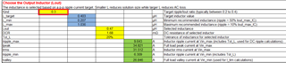
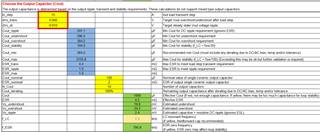
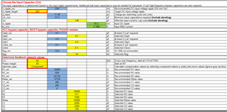
My customer designed the TPS546C20A as below.

TPS546C20A is used instead of TPS546C23 for U2 in the schematic.

3060.TPS546C20A.pdf

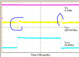
When the operation according to the load was tested using a loader, it operated normally only up to 15A.

Are there any problems with the above TPS546C20A design?

Please advise the cause of the issue and how to fix it.

Thank you.

JH

JH

  • Hello JH, 

    Can you please fill up the attached calculation tool for the device? 

    that should give a first pass of the SCH. 

    Also, please send me a plot of the abnormal current

     TPS546C20A_TPS546C23_Calculator_Checklist_1p0.xlsx

    Thanks 

    Tahar

  • Hello Tahar,

    Below is the calculation tool file that the customer replied.

    TPS546C20A_TPS546C23_Calculator_Checklist_1p0 (1).xlsx

    They said they couldn't change the values because they didn't understand the contents of the display items below.

    Thank you.

    JH

  • Hello JH, 

    Thank you for filling up the spread sheet. 

    Io_step is the expect load step when doing load transient. for example when going from 0 to 15A.

    DVo_Tran is the undershoot and overshoot during transient event of the VOUT

    and the DVO_DC, is basically the DC offset when going from light load to high load, typically the comes from the DC regulation of the device plus any drops in the traces. 

    Phase margin and Cross over frequency, 60K and 60C is the recommended  margin for this device

    Going back to your question about the not getting more than 15A. 

    The spread sheet entries looks good, nothing indicating an issue, please check the following: 

    • You can increase the LC resonant by decreasing  the number of COUT capacitors to 7 instead of 10. 
    • Regarding the inductor, please make sure the inductor is not saturating. inductor current ripple is ~10A. you will expetect upto 35A peak inductor current. 
    • The IOUT_OC_FAULT_LIMIT command sets the overcurrent threshold. The device uses inductor middle current value for overcurrent detecting. The current limit should be set to the maximum load current, plus the output capacitor charging current during start-up, plus some margin for load transients and component variation. The amount of margin required depends on the individual application, but a suggested point is between 20% and 40%. For your application, the maximum load current is 30 A plus about 0.5 A COUT charging. This design allows some extra margin, so an overcurrent threshold of min of 37 A should be selected.
    • Does PG toggles when the device loaded more than 15A? 
    • Please send me plot on the devices behaves when is not able to deliver full load, i want to see VOYT, Inductor current, VIN, and SW. 

    Thanks! 

    Tahar