This thread has been locked.

If you have a related question, please click the "Ask a related question" button in the top right corner. The newly created question will be automatically linked to this question.

BQ78350: CEDV Parameters and Operation

Part Number: BQ78350
Other Parts Discussed in Thread: GPCCEDV,

Hi,

I am struggling to understand what is going wrong with the CEDV gauging on my 78350 around the end of discharge and therefore how to improve it.

As background the battery is 9S LFP.

I have run through the learning cycles a few times with different load conditions, the latest calibration set that I have used was done with a low rate of 10A and a high rate of 100A and returns the following:

ProcessingType=1
NumCellSeries=9
CellTermV=2850
LearnSOC%=7
FitMaxSOC%=12
FitMinSOC%=6
ChemType=4

EMF 3261
EDVC0 121
EDVC1 0
EDVR1 470
EDVR0 2261
EDVT0 4820
EDVTC 11
VOC75 29871
VOC50 29619
VOC25 29185

file SOC error, % pass
roomtemp_lowrate.csv 0.835848428645379 1
roomtemp_highrate.csv -0.241990214888698 1
hightemp_lowrate.csv -0.314618964659832 1
hightemp_highrate.csv -0.350313002604034 1
lowtemp_lowrate.csv -0.818230169830177 1
lowtemp_highrate.csv 0.87776579492757 1

Deviations are within recomended range. CEDV parameters are suitable for programming the gauge

Battery Low % is set for the default 7%

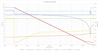
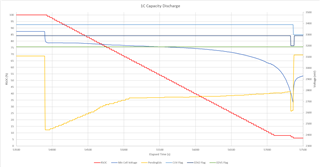
Having programmed these parameters if I do a full capacity discharge at 54A at room temperature, the gauge tracks well until it gets towards the end and then never drops below 6%.

Looking at it in more detail, the value of Pending EDV seems to fluctuate wildly and the battery only just flags EDV2 before the CUV point is hit (CUV is set for 2700mV).

If I look at my original calibration capture for room temp and calculate the voltages corresponding to 7%, 3% and 0% I get 3009, 2940 and 2830 from the high rate and  3156, 3037 and 2797 from the high rate.
As my test discharge is between the two rates I would therefore expect the CEDV values to sit somewhere between these (ie the compensated EDV2 would be somewhere between 3009 and 3156).

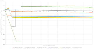
You can see on this graph that Pending EDV (Yellow) is way outside this range with the EDV2 point being anywhere between 3100 and 2445.

So, any idea what is going on and how this can be improved (other than reverting to fixed EDV)?

Thanks,

Simon

  • As a further update on this I have tried enabling fixed EDV0.

    This helps slightly, but mostly by masking the problem as it limits the CEDV range. It doesn't solve the underlying issue that the CEDV calculation is generating values that are clearly way out. TI are obviously very coy about disclosing the detail of the CEDV calculation, which would be fine if it actually worked or there was some way to see how to optimise the parameters beyond just using GPC.

     
    I've updated the original graph and added a calculated RSOC as well as the temperature. You can see how the Pending EDV tracks with the rising stack temperature through the second half of the discharge, but there is clearly more than temperature having an effect here (Note I also flipped the way that I was plotting the flags along the way as well compared to my original post).

    With Fixed EDV0 I now get the three EDV flags just about sequencing correctly, but too late which results in the plateau region in RSOC, although it does now at least hit 0%:

  • Hello Simon,

    What is the setting of EDV_CMP for this data?

    I would refer to the TRM section "End-of-Discharge Thresholds and Capacity Correction"

  • HI Shirish,

    EDV_CMP is set, ie CEDV is enabled.

    I am familiar with that section of the TRM, but it doesn't help here.

    I have all EDV hold times set for 2s (the end application is a high pulse load although here I am just testing with CC)

    The CEDV parameters are set according to the values returned by GPC as listed in the op.

    The EDV age factor is set to 18 as recommended for LFP in the TRM 'EDV Age Factor' section. That value is just taken on trust as there is no indication of how that may influence. 

    Overload current is set above the 1C discharge that I am testing against so CEDV should be generating new values which it appears to be doing.

    I am testing at currents and temperatures inside of the calibration data that went into the GPC. (Calibration cycles that went into GPC were done at C/5 and 2C at 10°C, 25°C and 40°. These tests are at 1C and 25°C) 

    In the original graph that I posted, you can see pending EDV varies wildly far outside any reasonable values. At the start of that discharge (when the battery was fully charged) the pending EDV value (which would be EDV2) plummets to less than 2300mV, despite GPC having been told that the CellTermVoltage was 2850mV. This essentially is the core problem here, I've been through GPC, got values back with indicative errors below 1% but when I test, the algorithm it's producing junk.

    So other than abandoning CEDV and just using fixed EDV values, how can this be improved?

  • Hello Simon,

    Can you confirm that the following instructions for GPCCEDV data were followed?

    The first rate should be average typical, and second should be average high for your application. Note that high rate should not be maximum peak current, but rather maximum average sustained rate that can practically occur in the application.

    Discharge does not have to be constant current, it can be any load pattern typical for your application, including constant power. It is OK to have zero current rows before and after the discharge.

  • Hi Shirish,

    The battery requirements have two distinct modes of operation.

    The first is a low rate constant power demand which is what I used for the low rate GPC data collection. The battery is 52Ah / 1.5kWh and this rate is 263W.

    The second mode of operation is an extreme pulse load (1000A peak) with very variable spacing. In the highest duty mode, this equates to an RMS of about 330A but this is only sustained for a maximum of 30s. The intent is that this high intensity / short duration demand would sit in the 'overload' region so that it doesn't interfere with the CEDV. Note that I am not currently testing in this manner so is not relevant to the issues that I am seeing, but is mentioned for context.

    For the 'high rate' GPC data collection therefore I chose an arbitrary 100A constant current discharge. I did also try running the data collection at 50A constant current, but the GPC tool returned a higher maximum error than with the 100A (1.4% rather than 0.8%). I have not tried using the parameters returned from the 50A data given that the metrics are worse.

    The other thing to probably mention is that a full capacity discharge at 100A does cause heating within the stack as you would expect. Typically the stack is about 15°C warmer at the end of the discharge which obviously has an effect on cell voltage. I had assumed that this is one of the things the GPC tool is trying to compensate for?

    The data that went into GPC was all continuous discharge, with short sections at the start/end of 0A.

  • Hello Simon,

    You can get a better match by discharge to a lower voltage for the log. Also is the thermistor closely coupled to the cell? It is important to get the cell temperature (which can be different from the temperature chamber due to self heating) in the log.

  • Hi Shirish,

    With regard to the thermistors, yes these are closely coupled to the cells. The pack is constructed from 18P modules of 26650 cells. Within each module there is a thermistor buried in the centre bonded to a cell. Three thermistors are then paralleled together to feed each of the TS inputs on the 76940 and the thermistor coefficients are set to produce correct results. Each of the three TS inputs is therefore an average of three cell modules which is the best that we can do within the limitations of the 76940, but it is definitely cell temperature and not chamber/environment.

    The end of discharge for the application is 2777mV, but I would like gauge 0 to be slightly higher hence setting CellTermV to 2850mV in GPC.

    CUV is set higher than I would have liked at 2700mV to ensure that the primary UV protection of the 78350 acts before the independent secondary protection at 2000mV under high pulse loads. 

    The data logs that I fed into GPC discharged to 2777mV to match the expected end of discharge point. When you say You can get a better match by discharge to a lower voltage for the log, how much lower do you suggest going? The CUV point is not far below this, but I could move CUV down to 2300mV and run down to that for the GPC log if you think that will help?

    If I do that is it sufficient to keep CellTermV set to 2850mV to tell GPC where gauge 0 should be?

    Any suggestions as well on what high rate to use? As I said at 100A I got better match statistics out of GPC, but it does raise the cell temp by about 15°C. Is that OK, or would that be better lower so that there is less self heating during discharge?

    Running the GPC log is expensive in terms of time and resources as it ties up the battery and test equipment for a full week, so if the answer to why the CEDV is not producing sensible estimates is to re-do the calibration log then I want to ensure that this is the last time.

  • Hello Simon,

    Check if the battery spec supports a discharge at such high current. With a battery capacity of 52AH and peak current of 1000A, the peak current draw is 20X. Are you able to share the battery spec?

    You can discharge till the cutoff voltage of the battery in the log to get a better match. The CellTermV is specified separately, so the log does not affect the actual termination if discharged below that. The high rate is 330A if that is the RMS for 30s. The self heating is expected and used by GPCCEDV to get a better match.  

    Also testing should be done with the actual load. A different load can affect EDV learning because the voltage drop points change.

  • Hi Shirish,

    I have created a new set of logs to use for GPC. To do this I reduced my CUV value from the normal 2700mV down to 2300mV and continued the discharge until this point.

    I have logged at three temperature (10°C, 25°C and 40°C).

    At each temperature I have logged at four different rates (12.5A, 25A, 50A = 1C and 100A).

    I have fed the different combinations into GPC and looked at the resulting errors and picked one of the lower combinations.
    I have then used the 25A data as the low rate and 50A data as the high rate and updated the 78350 with the parameters returned by the GPC tool.

    This is what I get back from GPC:
    GPC CEDV tool, rev=60
    Configuration used in present fit
    ProcessingType=1
    NumCellSeries=9
    CellTermV=2800
    LearnSOC%=7
    FitMaxSOC%=12
    FitMinSOC%=3
    ChemType=4
    ElapsedTimeColumn=0
    VoltageColumn=1
    TemperatureColumn=2
    CurrentColumn=3

    CEDV parameters resulting from the fit. If EDVV bit is set to 1, EMF and EDVR0 have to be multiplied by the number of serial cells when written to data flash

    EMF 3323
    EDVC0 210
    EDVC1 0
    EDVR1 596
    EDVR0 2204
    EDVT0 4729
    EDVTC 11
    VOC75 29869
    VOC50 29619
    VOC25 29181


    Recommended SOC deviation tolerance at EDV2 point is < 5% for low temperature and <3% for room and high temperature

    Deviations for this set of parameters are given below for each file

    file SOC error, % pass
    roomtemp_lowrate.csv 0.0568911307485473 1
    roomtemp_highrate.csv 0.192596775235947 1
    hightemp_lowrate.csv -1.02462065198633 1
    hightemp_highrate.csv -1.37170335587172 1
    lowtemp_lowrate.csv -0.542914433052816 1
    lowtemp_highrate.csv 1.206387494866 1

    Deviations are within recomended range. CEDV parameters are suitable for programming the gauge

    Note that I have set CellTermV to 2800mV here which is the point I expect to get 0 out of the fuel gauge.

    After updating the CEDV coefficients I have reset my CUV value back to 2700mV and run some test cycles.

    On the second full cycle I have examined the discharge to see how the CEDV is doing.

    When the discharge starts, PendingEDV drops to 2640mV - given that I have set CellTermV to 2800, why is CEDV returning values out of range?

    As the discharge proceeds, PendingEDV rises slowly, the shape of the curve closely follows the temperature as the stack warms through the discharge.

    The RSOC value tracks down and then sticks at 8% (presumably because EDV2 is never reached although BatteryLow % is set at 7%)

    The stack then reaches the CUV cut-off point before reaching EDV2, so none of the EDV flags get set.

    The graph of this is shown below.

    So I'm still stuck with my original problem that CEDV just does not work even under benign conditions that are within the envelope of the learning cycles and I've wasted a load more time without getting any improvement at all. 

    Why does CEDV not work?

  • Hello Simon,

    It looks like the design capacity may not be set correctly.

    If you can share log and GG files, then we can try to figure out what is going wrong.

  • Hi Shirish,

    If I plot RC rather than RSOC I still get a good match between the 78350 and the actual as reported by the Digatron (calibrated battery cycler) until the end of discharge where CEDV should be kicking in.

    Log files and gg attached.

    Note that the 78350 operates with a factor of 50 scaling on all current based measurements (eg an actual current of 50A reports as 1000mA and a reported capacity of 1040mAh equates to an actual capacity of 52Ah). 

    78350 230531 ENG001 after BH learning 50 25 pair.gg.csv

    1172.GPCPackaged.zip

    7875.GPCPackaged-report.zip

    WBH Evaluation - no links.xlsx

  • Hello Simon,

    Thank you. I will check it on Monday.

  • Hello Simon,

    In reviewing the log file i found that MaxError is set to 8% when FCC is updated which means that FCC is being capped

    TRM 17.14 0x0C MaxError()

    The time and rate of discharge in the log are within the designed limits.

    This also supports your theory of EDV2 not being computed correctly. I will need to dig more into this.

  • [deleted]
  • Sorry for the delay. Our expert is out of office

  • [deleted]
  • We may have an update tomorrow or Monday

  • I will follow up on this today and let you know

  • I don't see any problem with GPC calculation, all submited data and response look normal. One thing that could be potential issue is high voltage that is used in the pack, it is 9 serial cells (which is not a common scenario for CEDV), and so there is some potential issue with an overflow in the computations of EDV2 when values of voltage are approaching MaxInt, resulting in "capping" of some intermediate value. If this is the case, we have to refer it to firmware team.

    As a brief check of this idea, you could try to change EDVV bit setting to 1. If EDVV bit is set to 1, EMF and EDVR0 have to be multiplied by the number of serial cells when written to data flash. As computations will be differently scaled in this case, we could see that original problem will disappear, or the cap that is happening internally will become more evident when everything is scaled to pack voltage.

  • Hi Yevgen,

    Thanks for the reply.

    I'm surprised that you say that CEDV is not common for 'high voltage' packs given that the 78350 and other CDEV gauges are marketed for up to 16 cell packs. If it is the case that this is never going to work, then I'd rather just move on and reconfigure the gauge for fixed EDV and accept the limitations. When I look at the data however given the temperature sensitivity of the voltage response of LFP chemistry it seems tailor made for a CEDV approach hence why I have persisted so far.

    You suggest setting EDVV and rescaling the EMF and R0 values, but I can't find that bit in the 78350 TRM, which DF register is it in? 

    When I read the TRM it seems to suggest that the CEDV calculation is only working at the single cell level anyway. 9.1.7 says that The
    bq78350-R1 uses the lowest, single-cell value from individual cell voltage measurements for EDV threshold comparison when CEDV Gauging Configuration [EDV_EXT_CELL] = 0. However, if this bit = 1, then the ExternalCellVoltage() is used.

    I have tried both options for EDV_EXT_CELL and currently have this set to 1.

  • Hello Simon,

    It looks like fixed EDV is a better option if you have already seen that it works for your application.

  • Hi,

    Was there any update on how to get CEDV to give sensible EDV values?

    In the meantime I have created a set of fixed EDV points aiming to reduce the error in the more likely discharge scenarios.

     I have then run some characterisation on these to see how it looks when I vary the rate and the temperature.

    You can see how at low temperature / high rate, where the voltage is supressed, EDV2 is hit early causing the SoC to jump to match the Battery Low % value that corresponds to EDV2.

    This is the sort of scenario where I would expect CEDV to improve matters, but that assumes that the CEDV algorithm can come up with a reasonable set of parameters in the first place.

  • Hello Simon,

    Per Yevgen, there is no problem with the CEDV data obtained from GPCCEDV.

    The problem may be in the firmware calculations that is resulting in "capping".  Not sure if this helps but there seems to be no other explanation.